Ink rubber peeling device

A technology of rubber and ink, applied in the direction of spraying devices, etc., can solve the problems of slow production speed, low cleaning efficiency, and tired feeling of rope rubber heads, and achieve the effects of saving manpower and time costs, improving production efficiency, and convenient placement

Pending Publication Date: 2020-05-19
广东康派环创科技有限公司
View PDF0 Cites 0 Cited by
  • Summary
  • Abstract
  • Description
  • Claims
  • Application Information

AI Technical Summary

Problems solved by technology

The cleaning stage is due to the fact that the hook after one use is also soaked in ink during the oil immersion stage, so it is necessary to scrape off the dry ink on the hook one by one, including the rope hanging stage, head cutting stage, oil replenishment stage and cleaning stage All require employees to complete the ropes one by one and clean the hooks one by one according to the marks of the previous process. The repetitive labor of the employees is frequent, and it is easy to feel tired. At the same time, the efficiency is low, and the production speed of the rubber head of the rope is slow.
At present, the rope winding method is mainly used instead of the hanging rope method to complete the production process of the rope rubber head. In the rope winding method, the bottom rod of the rope winding frame will be wrapped with a layer of ink skin after the oil immersion stage. If it is not cleaned, it will affect For the next production and use of the rope winding frame, the existing cleaning method is to clean one by one by manual hand-held knives. Manual cleaning takes a lot of time, the cleaning efficiency is low, and it also affects the production process of the rope rubber head

Method used


Image

  • Ink rubber peeling device
  • Ink rubber peeling device
  • Ink rubber peeling device

Examples


Embodiment Construction

[0027] In order to facilitate the understanding of the present invention, the present invention will be described more fully below with reference to the associated drawings. Preferred embodiments of the invention are shown in the accompanying drawings. However, the present invention can be embodied in many different forms and is not limited to the embodiments described herein. On the contrary, these embodiments are provided to make the understanding of the disclosure of the present invention more thorough and comprehensive.

[0028] In the description of the present invention, it should be understood that the terms "center", "upper", "lower", "bottom", etc. are used in the present invention. The orientation or positional relationship indicated by "inner", "outer", etc. is based on the orientation or positional relationship shown in the drawings, and is only for the convenience of describing the present invention and simplifying the description, rather than indicating or imply...


PUM


Abstract

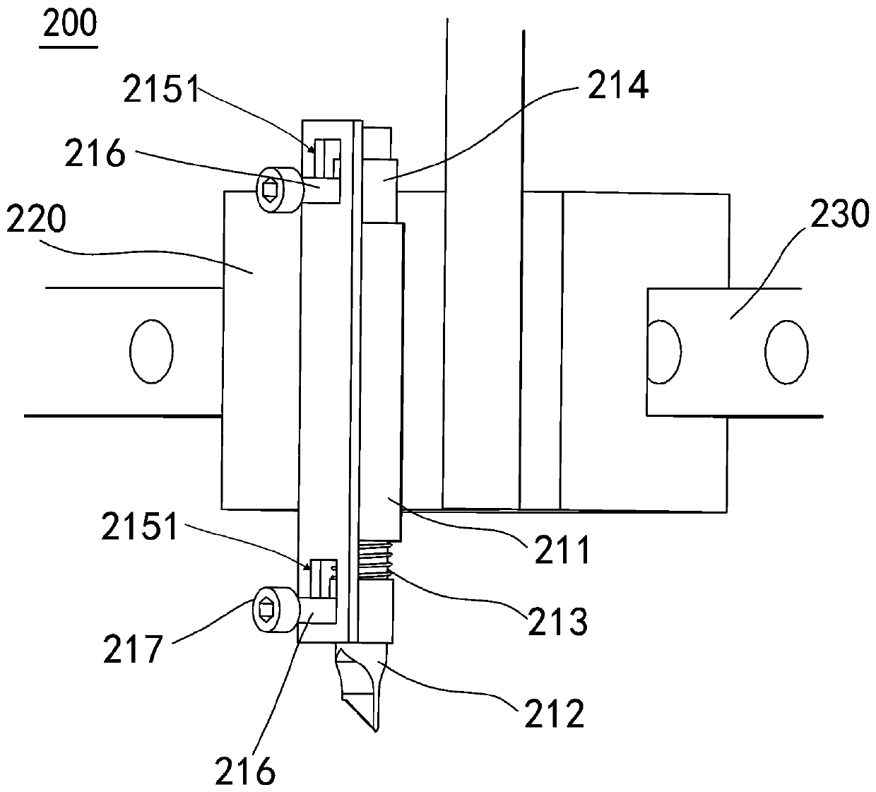
The invention discloses an ink rubber peeling device. The ink rubber peeling device includes a supporting mechanism and a cutting mechanism. The supporting mechanism includes a supporting seat. A plurality of placement grooves distributed in a row are formed in the upper surface of the supporting seat, and the axes of the placement grooves are inclined at an angle with the upper surface of the supporting seat. The cutting mechanism includes a cutter assembly, a sliding block and a guide rail. The guide rail is arranged on the supporting seat and extends in the distribution direction of the placement grooves, and the sliding block is slidably connected to the guide rail and located above the placement grooves. The cutter assembly is movably connected to the sliding block. The ink rubber peeling device is used for assisting workers to clean ink rubber on rope winding frame bottom rods, can save a lot of manpower and time, and has high cleaning efficiency. The ink rubber peeling device solves the problems that manual cleaning takes a lot of time, the cleaning efficiency is low, and a production process of rope tape rubber heads is further affected due to the fact that the ink rubber is cleaned manually one by one by people holding cutters in traditional methods.

Description

technical field [0001] The invention relates to the textile field, in particular to an ink rubber peeling device. Background technique [0002] In the textile field, the production process of rope rubber head includes marking stage, hanging rope stage, oil immersion stage, drying stage, head cutting stage, oil replenishment stage and cleaning stage. The marking stage is to mark the corresponding distance of each section on a whole rope according to the length of the rope to be manufactured. The rope hanging stage is to hang the marked section of the rope on the hook according to the mark on the rope. The oil immersion stage is to immerse a row of hooks with ropes in the ink. In the drying stage, the ink-soaked rope is placed in a drying room for a period of time to fully dry the ink. The cutting stage is to cut the dried rope at the end of the rope soaked in ink; the oiling stage is to soak the cut of the cut rope with ink so that the ink completely wraps one end of the r...

Claims


Application Information

Patent Timeline
Patent Type & Authority Applications(China)
IPC IPC(8): B05B15/50
CPCB05B15/50
Inventor 李杰杜童德汤建华程仕德曾武薛矛冯世亮
Owner 广东康派环创科技有限公司
Why Eureka
Try Eureka