Millimeter wave processing device and millimeter wave scanning system

A processing device, millimeter wave technology, applied in radio wave measurement systems, measurement devices, reflection/re-radiation of radio waves, etc., can solve problems such as the inability to meet the application of three-dimensional imaging systems

Pending Publication Date: 2020-05-15
北京华研微波科技有限公司
View PDF5 Cites 2 Cited by
  • Summary
  • Abstract
  • Description
  • Claims
  • Application Information

AI Technical Summary

Problems solved by technology

The existing millimeter-wave processing devices are basically narrow-band systems, so they cannot meet the requirements of 3D imaging systems

Method used


Image

  • Millimeter wave processing device and millimeter wave scanning system
  • Millimeter wave processing device and millimeter wave scanning system
  • Millimeter wave processing device and millimeter wave scanning system

Examples


Embodiment Construction

[0046] The present invention is described below based on examples, but the present invention is not limited to these examples. In the following detailed description of the invention, some specific details are set forth in detail. The present invention can be fully understood by those skilled in the art without the description of these detailed parts. To avoid obscuring the essence of the present invention, well-known methods, procedures, procedures, and components have not been described in detail.

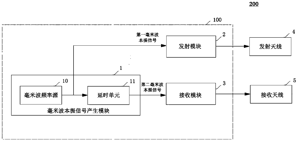
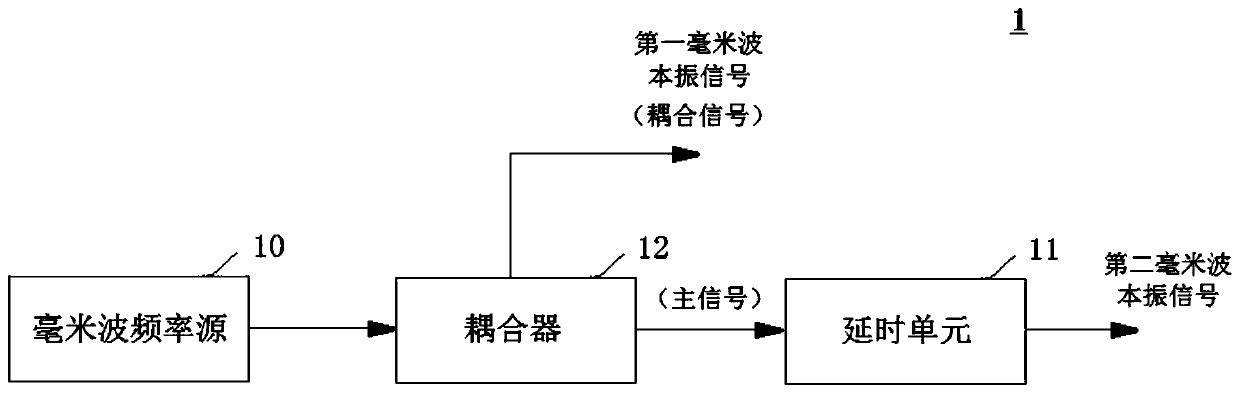
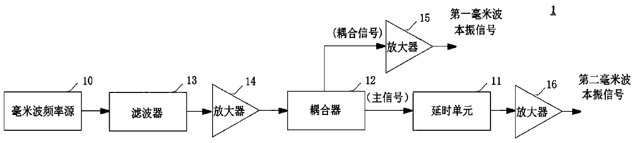
[0047] combine Figure 1-7 The millimeter wave scanning system and the millimeter wave processing device of the present invention will be described. figure 1 It is a configuration block diagram of the millimeter wave scanning system according to the present invention. figure 2 It is a configuration block diagram of a millimeter wave local oscillator signal generating module according to an embodiment of the present invention. image 3 It is a configuration block diagram of a ...


PUM


Abstract

The invention provides a millimeter wave processing device, which is used for processing an emission signal emitted to an object to be scanned and processing an echo signal reflected back from the object to be scanned, and comprises a millimeter wave local oscillation signal generation module, a transmitting module and a transmitting module. The millimeter wave local oscillator signal generation module comprises a millimeter wave frequency source used for generating a first millimeter wave local oscillator signal; and a time delay unit used for carrying out time delay processing on the first millimeter wave local oscillator signal generated by the millimeter wave frequency source so as to generate a second millimeter wave local oscillator signal. The transmitting module mixes a predetermined baseband signal with a first millimeter wave local oscillator signal generated by a millimeter wave frequency source so as to convert the predetermined baseband signal into the transmitting signalto be transmitted. And the transmitting module mixes the second millimeter wave local oscillator signal generated by the time delay unit with the echo signal received by the receiving module so as toconvert the echo signal into a to-be-processed intermediate frequency signal.

Description

technical field [0001] The invention relates to a millimeter wave processing device and a millimeter wave scanning system. Background technique [0002] With the development of radar technology, Synthetic Aperture Radar (SAR) has expanded from purely military applications to civilian applications, from outer space to the ground for long-distance detection and even close-range detection of human dangerous goods, from flat static two-dimensional Image reconstruction develops into stereoscopic three-dimensional dynamic imaging. Its development is inseparable from the progress of microwave transceiver channel technology. Especially from the current development of microwave transceiver channel, its working frequency band is getting higher and higher, its working frequency band is getting wider and wider, its integration level is getting higher and higher, and its electrical performance is getting better and better. Excellent, the cost is getting lower and lower. [0003] For th...

Claims


Application Information

Patent Timeline
IPC IPC(8): G01S13/90G01S7/41G01S7/35
CPCG01S13/90G01S7/41G01S7/352G01S7/35
Inventor 张元超
Owner 北京华研微波科技有限公司
Why Eureka
Try Eureka