
Large-component three-dimensional measurement method based on line structured light and industrial robot

An industrial robot, three-dimensional measurement technology, applied in the field of computer vision, can solve the problems of poor control of splicing error, single splicing method, complex calibration process, etc., to achieve the effect of low measurement environment requirements, simplified calibration process, and broad development prospects.

Active Publication Date: 2020-05-15
NANJING UNIV OF SCI & TECH
View PDF6 Cites 26 Cited by
  • Summary
  • Abstract
  • Description
  • Claims
  • Application Information

AI Technical Summary

Problems solved by technology

At present, laser trackers and industrial robots are often used for 3D stitching, which makes the absolute positioning accuracy of any point in space high, but the additional laser tracker is expensive
(2) Through the turntable method of accurately measuring the rotation angle, the splicing method of this turntable method is relatively simple and can only measure specific objects
(3) The frame positioning stitching method that calibrates the positional relationship between multiple cameras in advance, the stitching method calibration process is complicated, and can only be applied to the measurement of specific scenes
(4) The splicing method through the optical positioning and tracking of the splicing target. Due to the introduction of the splicing camera, the splicing error is not easy to control.
(5) The multi-view label positioning splicing method of pasting marker points on the surface of the measured object. This splicing method is simple and practical, and is currently the most widely used three-dimensional splicing method in actual engineering. However, it is time-consuming because of the need to paste mark points on the surface of the object. Laborious, can not completely achieve non-contact measurement

Method used


Image

  • Large-component three-dimensional measurement method based on line structured light and industrial robot
  • Large-component three-dimensional measurement method based on line structured light and industrial robot
  • Large-component three-dimensional measurement method based on line structured light and industrial robot

Examples


Embodiment

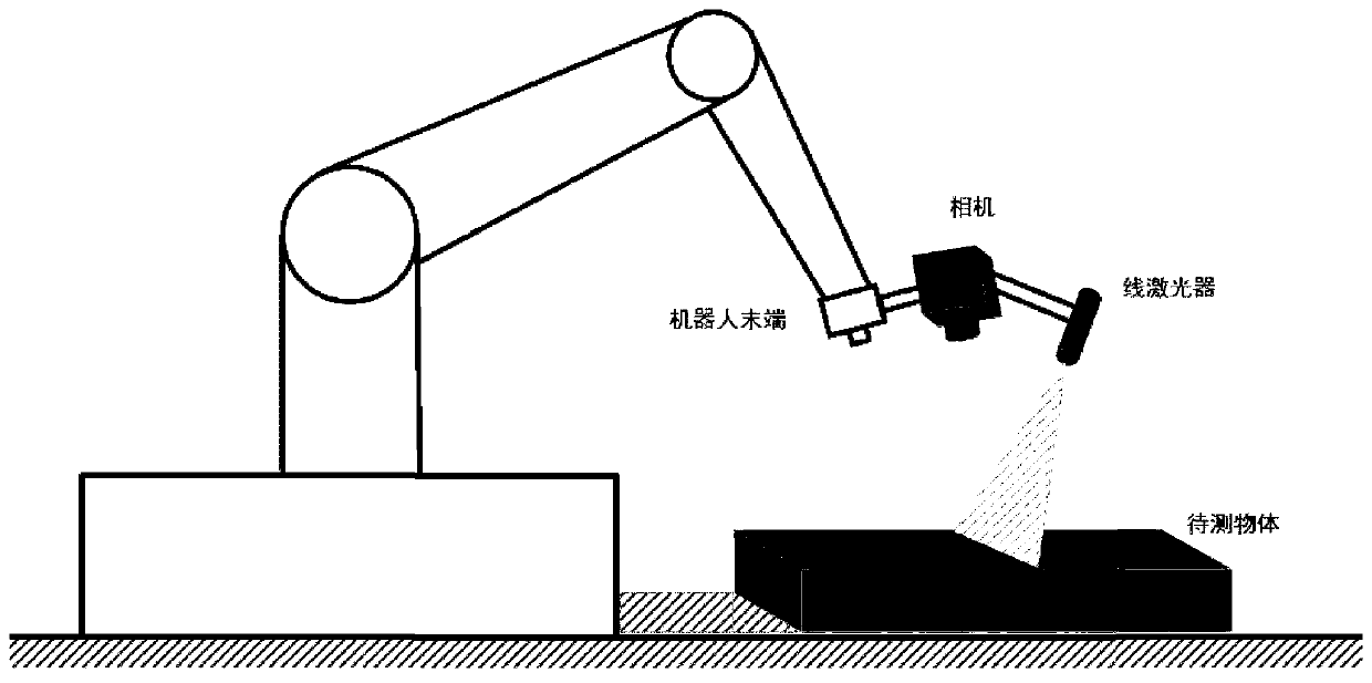
[0056] The large component three-dimensional measurement system of this embodiment is composed of industrial robots, cameras, line lasers and computers. The robot is the ERER-MA02010-A00-C model industrial robot of Yaskawa. The relevant parameters of the robot are as follows: The positioning accuracy is 0.08mm, the vertical elongation is 3649mm, and the horizontal elongation is 2010mm. The camera is an industrial camera, the model is Basler acA1920-40gm, and the laser is a line laser with 200mw power and 650nm wavelength. The camera and line laser are mounted on the end of the robot to form a line structured light 3D measurement system. The computer is connected to the camera and the control cabinet of the robot to obtain the line laser image and the attitude data of the robot. The three-dimensional measurement method of large components includes the following steps:

[0057] Step 1: Fix the camera 1 and the laser at the end of the Yaskawa robot, and take another camera 2 of...


PUM

PropertyMeasurementUnit
Diameteraaaaaaaaaa

Abstract

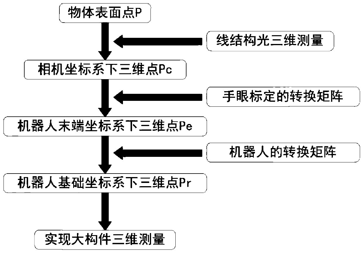
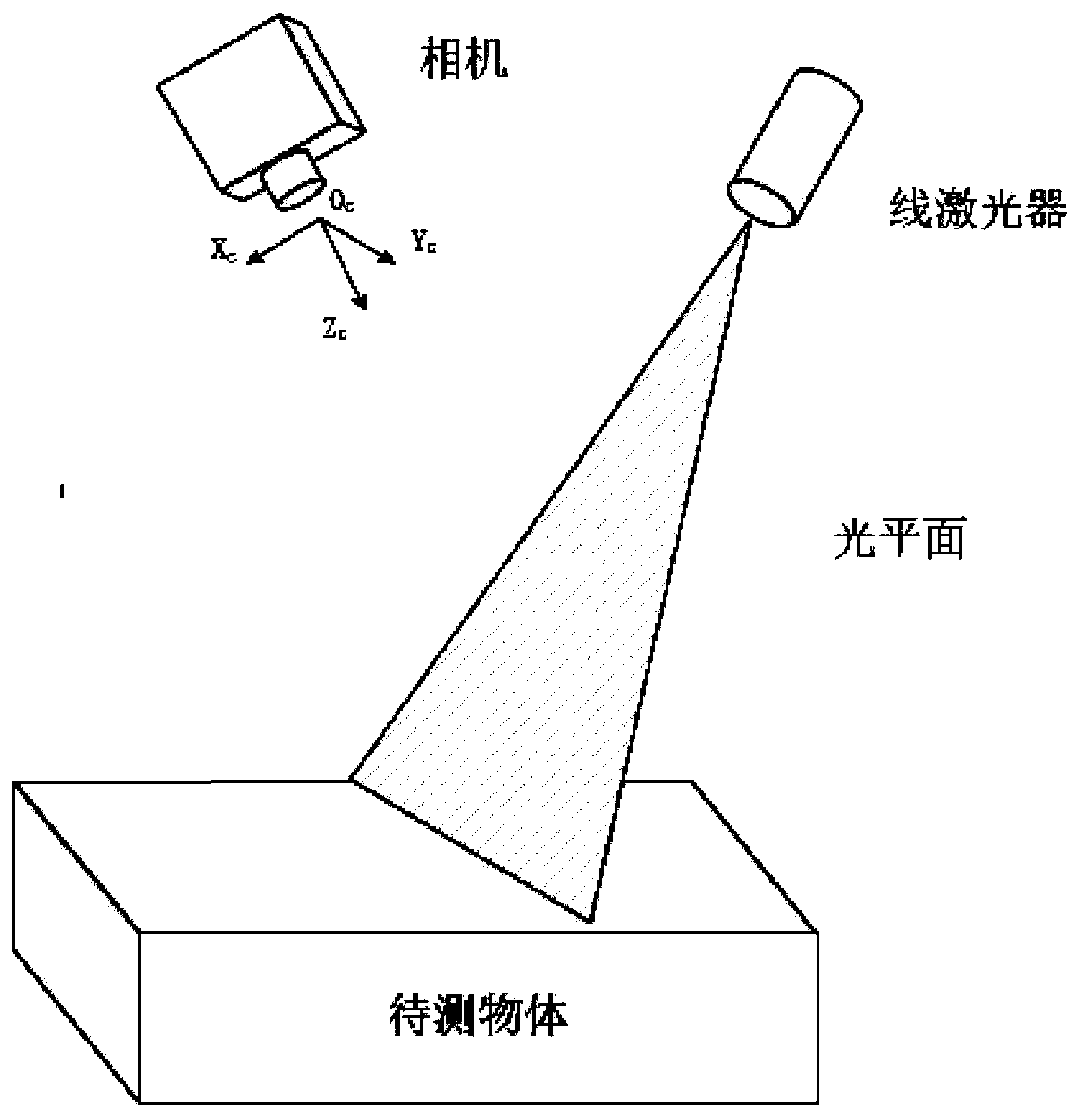
The invention discloses a large-component three-dimensional measurement method based on line structured light and an industrial robot, and the method consists of two parts: three-dimensional data acquisition of single measurement and three-dimensional data splicing between multiple measurements. According to the invention, the line structured light three-dimensional measurement technology and therobot hand-eye calibration technology are combined, the line structured light three-dimensional measurement system is used for obtaining three-dimensional data of single measurement, and robot hand-eye calibration realizes three-dimensional data splicing among multiple measurements. According to the method for calibrating the monocular line structured light plane under the assistance of the binocular camera, the line calibration process is simplified, and the line reconstruction precision is improved; a spatial circle fitting method is adopted to fit the sphere center coordinates of the standard sphere, so that the light plane can be any plane equation, the application range of the standard sphere hand-eye calibration method is expanded, and the measurement method can accurately reconstruct a target three-dimensional point cloud model.

Description

technical field [0001] The invention belongs to the field of computer vision, and in particular relates to a three-dimensional measurement method for large components based on line structured light and industrial robots. Background technique [0002] In large-scale three-dimensional shape measurement, the visual method has become one of the most important measurement methods due to its advantages of non-contact, high speed, high precision, and easy automation. In actual measurement, due to the limited field of view of the visual sensor or the mutual occlusion of the measured surfaces, there will be visual blind spots, and it is impossible to obtain all the information of the object surface at one time. Therefore, it is necessary to divide the large measured shape into multiple small areas, perform block unit measurement from different angles, and then use splicing technology to stitch together all the unit measurement results to construct the overall three-dimensional shape ...

Claims


Application Information

Patent Timeline
IPC IPC(8): G01B11/25
CPCG01B11/2504G01B11/25
Inventor 韩静赵壮柏连发张毅黄煜彭冲冲王景何丰郴王兴国
Owner NANJING UNIV OF SCI & TECH
Learn More