Air-water heat exchanger for cooling equipment

A technology for cooling equipment and heat exchangers, applied in the direction of heat exchanger types, indirect heat exchangers, heat exchange equipment, etc., can solve problems such as hidden safety hazards of the whole equipment, and achieve the effect of improving safety performance and service life

Inactive Publication Date: 2020-05-15
JIANGSU JOSUN SCI&TECH CO LTD
View PDF7 Cites 0 Cited by
  • Summary
  • Abstract
  • Description
  • Claims
  • Application Information

AI Technical Summary

Problems solved by technology

[0003] In order to solve the safety hazards caused by the water collection problem of the heat exchanger in the prior art to the whole equipment, the purpose of the present invention is to provide an empty water heat exchanger for cooling equipment with a water collection tank

Method used


Image

  • Air-water heat exchanger for cooling equipment
  • Air-water heat exchanger for cooling equipment
  • Air-water heat exchanger for cooling equipment

Examples


Embodiment Construction

[0015] Below in conjunction with accompanying drawing, the specific embodiment of the present invention is described in further detail:

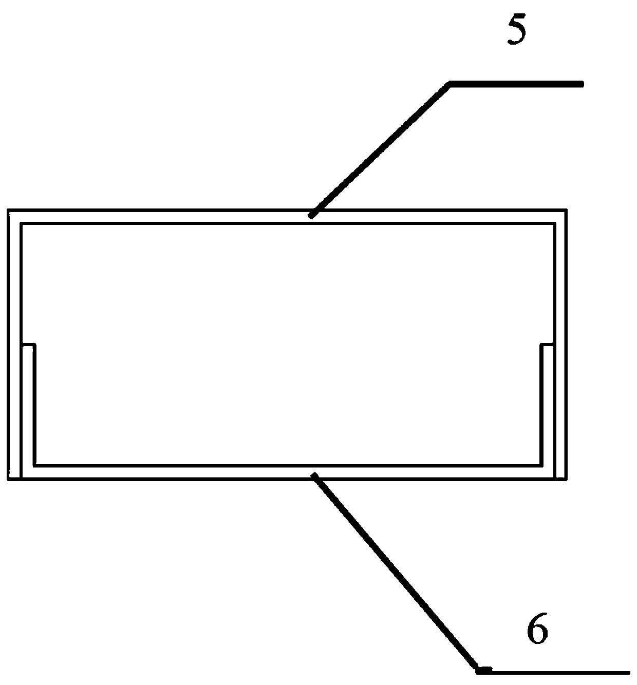
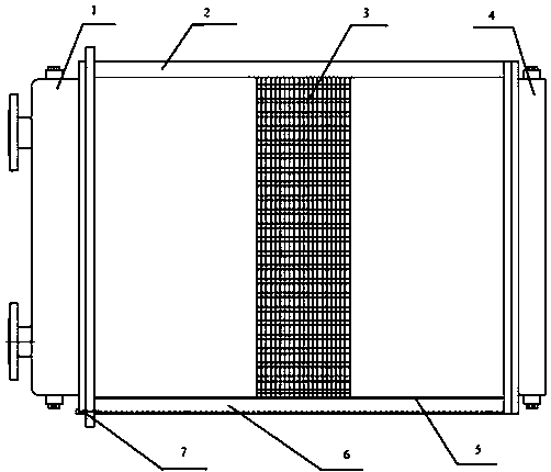
[0016] As shown in the figure, an air-to-water heat exchanger for cooling equipment includes a box body 2, and the front and rear sides of the box body are provided with air inlets and air outlets for heat exchange in and out of air. There are left and right water chambers 1 and 4 on both sides of the box body. The cooling water inlet and cooling water outlet are installed on the end surface of the left water chamber 1. The cooling water inlet is located above the cooling water outlet, and a partition is set in the middle of the left water chamber. , the cooling water inlet and outlet are separated into two independent cavities, the heat exchange core 3 is installed in the box body 2, and the heat exchange core 3 is a heat exchange tube group composed of multiple heat exchange tubes. Covered with fins, the two ends of each heat exchange tube...


PUM


Abstract

The invention relates to an air-water heat exchanger for cooling equipment. An air inlet and an air outlet are formed in the front side and the rear side of a box body, wherein a left water chamber and a right water chamber are arranged on the two sides of the box body; a cooling water inlet and a cooling water outlet are formed in the end face of the left water chamber; the cooling water inlet ispositioned above the cooling water outlet; the cooling water inlet and the cooling water outlet are separated by a partition plate; a heat exchange core body is arranged in the box body; the heat exchange core body comprises a heat exchange pipe set composed of a plurality of heat exchange pipes; the two ends of each heat exchange pipe of the heat exchange pipe set communicate with the left waterchamber and the right water chamber; a water baffle is arranged on the bottom face of the box body; a plurality of water baffle holes are formed in the water baffle; and a water collecting groove isformed in the bottom of the water baffle. The water collecting groove is additionally designed in the heat exchanger, condensate water or leaked cooling liquid can be rapidly collected, the equipmentis maintained through a water leakage alarm device in the first time, the safety performance of the equipment is improved, and the service life of the equipment is prolonged.

Description

technical field [0001] The invention relates to air-water cooling equipment, in particular to a novel air-water heat exchanger for cooling equipment. Background technique [0002] At present, the air-water heat exchanger used in the air-water cooling equipment does not have a water collection tank itself, but a water collection tank is installed in the whole equipment, which will cause the liquid leaked from the heat exchanger to not flow into the water collection tank in time, and during the collection process There is a risk of liquid leakage and incomplete collection, and the safety and service life of cooling equipment will not be improved. Contents of the invention [0003] In order to solve the potential safety hazard caused by the water collection problem of the heat exchanger in the prior art to the complete equipment, the purpose of the present invention is to provide an empty water heat exchanger for cooling equipment with a water collection tank. [0004] For a...

Claims


Application Information

Patent Timeline
IPC IPC(8): F28D1/04F28F17/00F28F27/00
CPCF28D1/04F28F17/005F28F27/00F28F2265/16
Inventor 常宇飞殷昌盛张嘉正顾政
Owner JIANGSU JOSUN SCI&TECH CO LTD
Why Eureka
Try Eureka