A bonding equipment for LED light source module and base
A technology of LED light source and base, applied in the direction of light source, mechanical equipment, light source fixing, etc., can solve the problems of cumbersome operation process and low work efficiency, and achieve the effect of simple operation and improved work efficiency
- Summary
- Abstract
- Description
- Claims
- Application Information
AI Technical Summary
Problems solved by technology
Method used
Image

Examples
Embodiment 1
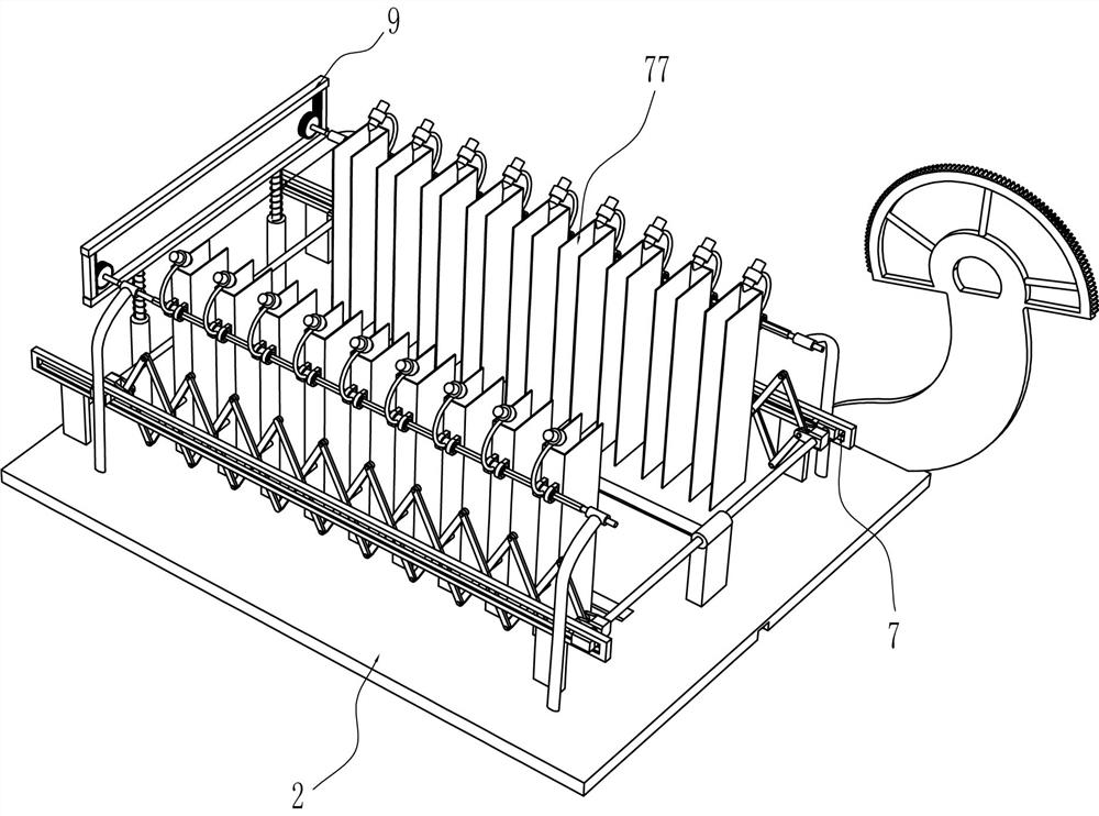
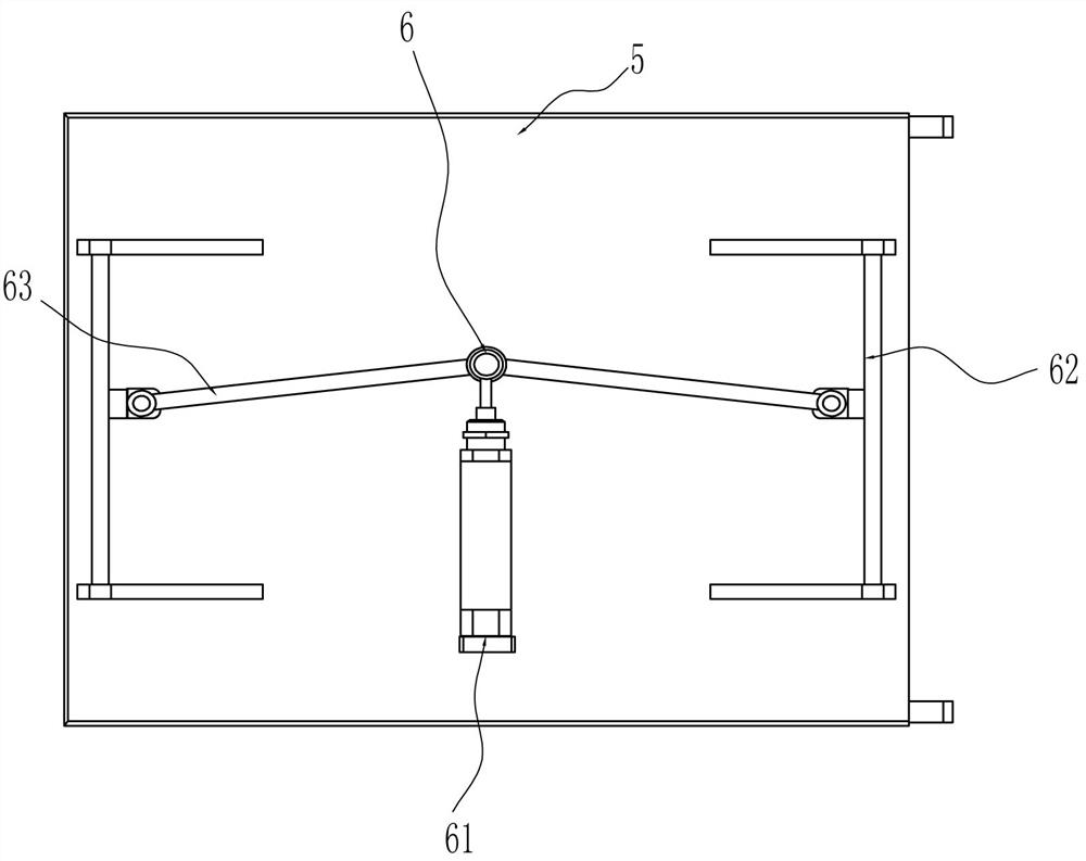
[0024] A kind of bonding equipment of LED light source module and base, such as Figure 1-5 As shown, it includes a base 1, a table top 2, a support rod 3, a support plate 4 and a rotating plate 5. The top of the base 1 is connected with a table 2, the left side of the top of the base 1 is connected with a support rod 3, and the left side of the top of the table 2 is connected with a support. Plate 4, supporting plate 4 is hingedly connected with rotating plate 5, rotating plate 5 is in contact with support bar 3, also includes clamping assembly 6 and adjustable distance material preparation mechanism 7, rotating plate 5 is provided with clamping assembly 6, table top 2 is provided with adjustable distance material preparation mechanism 7.
[0025] The clamping assembly 6 includes a cylinder 61, a U-shaped slide bar 62, a connecting rod 63 and a splint 64. The bottom of the rotating plate 5 is equipped with a cylinder 61, and the left and right sides of the rotating plate 5 ar...
Embodiment 2
[0029] On the basis of Example 1, such as figure 1As shown, a drive assembly is also included, the drive assembly includes a fixed plate 10, an arc rack 11, a reduction motor 12 and a drive gear 13, a reduction motor 12 is installed on the top of the rotating plate 5, and a fixed plate 10 is connected to the top of the table top 2. The top of the fixed plate 10 is connected with an arc rack 11, and the center of circle position of the arc rack 11 is consistent with the hinge point of the rotating plate 5 and the support plate 4. The output shaft of the reduction motor 12 is connected with a drive gear 13, and the drive gear 13 is connected to the The arc rack 11 meshes.
[0030] When needing to rotate rotating plate 5, can start deceleration motor 12 to drive driving gear 13 to rotate, driving gear 13 rotates and drives decelerating motor 12 to move through arc rack 11, and decelerating motor 12 drives rotating plate 5 to rotate when moving, and rotating plate 5 Rotate along ...
Embodiment 3
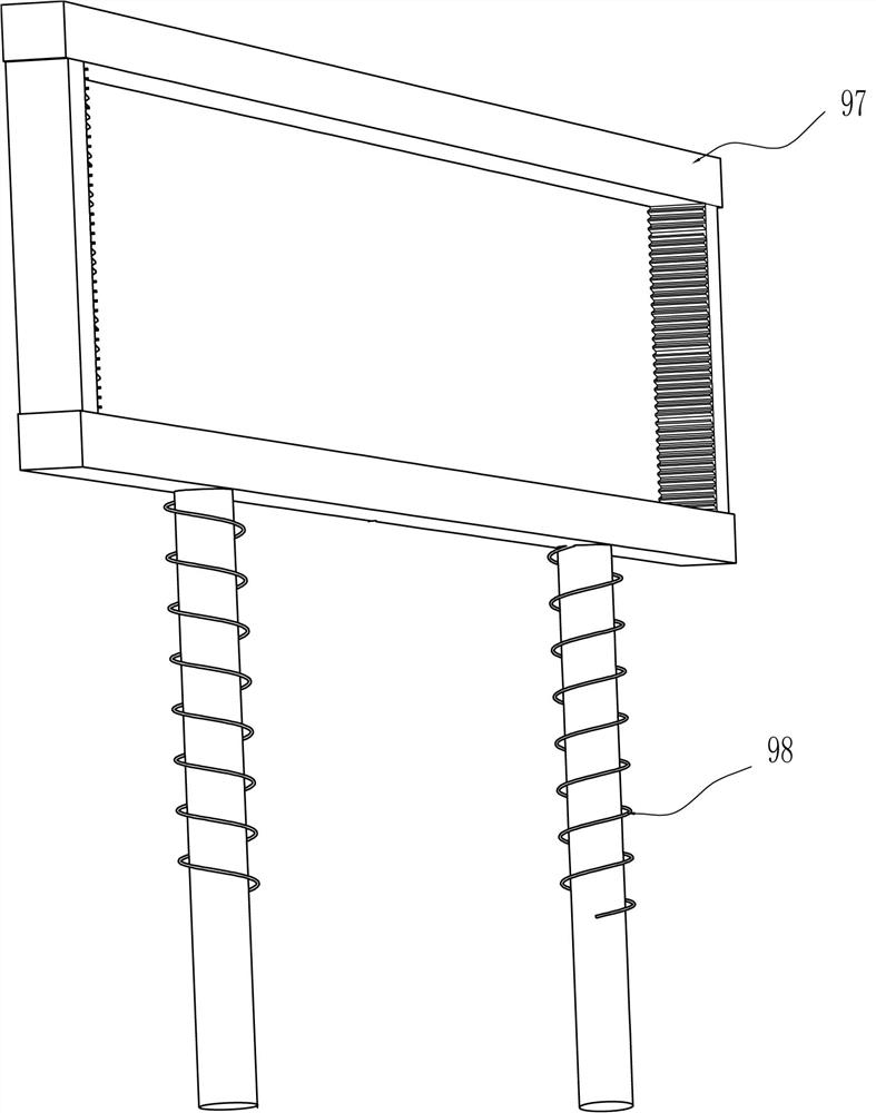
[0034] On the basis of Example 2, such as Figure 5 , Image 6 with Figure 8 Shown, also comprise dispensing mechanism 9, dispensing mechanism 9 includes stay cord 90, support bearing 91, rhombus rod 92, axle sleeve 93, shower nozzle 94, cylindrical gear 95, sliding tube 96, rack frame 97, thin Support springs 98 and pulleys 99, both sides of the front and rear sides of the table top 2 are symmetrically connected with support bearings 91, and the support bearings 91 on both sides are located at the outsides of the sliding frames 71 on both sides, and the support bearings 91 tops on the front and rear sides are connected with Rhombus rod 92, the upper part of the outer side of the semi-limiting housing 77 is connected with a support seat, and a shaft sleeve 93 is connected in a rotational manner in the support seat. The inside of the shaft sleeve 93 is arranged in a rhombus shape. A spray nozzle 94 is connected, a cylindrical gear 95 is connected to the right end of the rhom...
PUM
 Abstract
Description
Claims
Application Information
 - R&D
- Intellectual Property
- Life Sciences
- Materials
- Tech Scout
- Unparalleled Data Quality
- Higher Quality Content
- 60% Fewer Hallucinations
Browse by: Latest US Patents, China's latest patents, Technical Efficacy Thesaurus, Application Domain, Technology Topic, Popular Technical Reports.
© 2025 PatSnap. All rights reserved.Legal|Privacy policy|Modern Slavery Act Transparency Statement|Sitemap|About US| Contact US: help@patsnap.com