Steel bar bending equipment and method for building engineering

A technology for construction engineering and steel bars, applied in the field of steel bar bending equipment used in construction engineering, can solve the problems of low stability, reduced service life of the drive motor, burnt out of the drive motor, etc., achieve convenient and accurate control, prevent excessive load, The effect of efficient bending transmission

Inactive Publication Date: 2020-05-15
刘丽
View PDF10 Cites 3 Cited by
  • Summary
  • Abstract
  • Description
  • Claims
  • Application Information

AI Technical Summary

Problems solved by technology

[0003] When the existing steel bar bending machine is in use, the steel bar is usually directly placed on the disc, and the rotation of the pivot pin is used to force it to rotate and bend. First, the length of the steel bar is not positioned during bending, which is inconvenient for the length of the steel bar to be bent. Specific control leads to different specifications of bending parts, which is inconvenient for on-site construction. Secondly, when bending long steel bars, the stability of long steel bars is poor, and manual support is required. The stability is low, the manual labor intensity is high, and the processing of steel bars is inconvenient. Finally, when the steel bars are bent, the drive motor needs to provide a large torsional force. The long-term overload of the drive motor will reduce the service life of the drive motor, seriously will cause the drive motor to burn out

Method used


Image

  • Steel bar bending equipment and method for building engineering
  • Steel bar bending equipment and method for building engineering
  • Steel bar bending equipment and method for building engineering

Examples


Embodiment 1

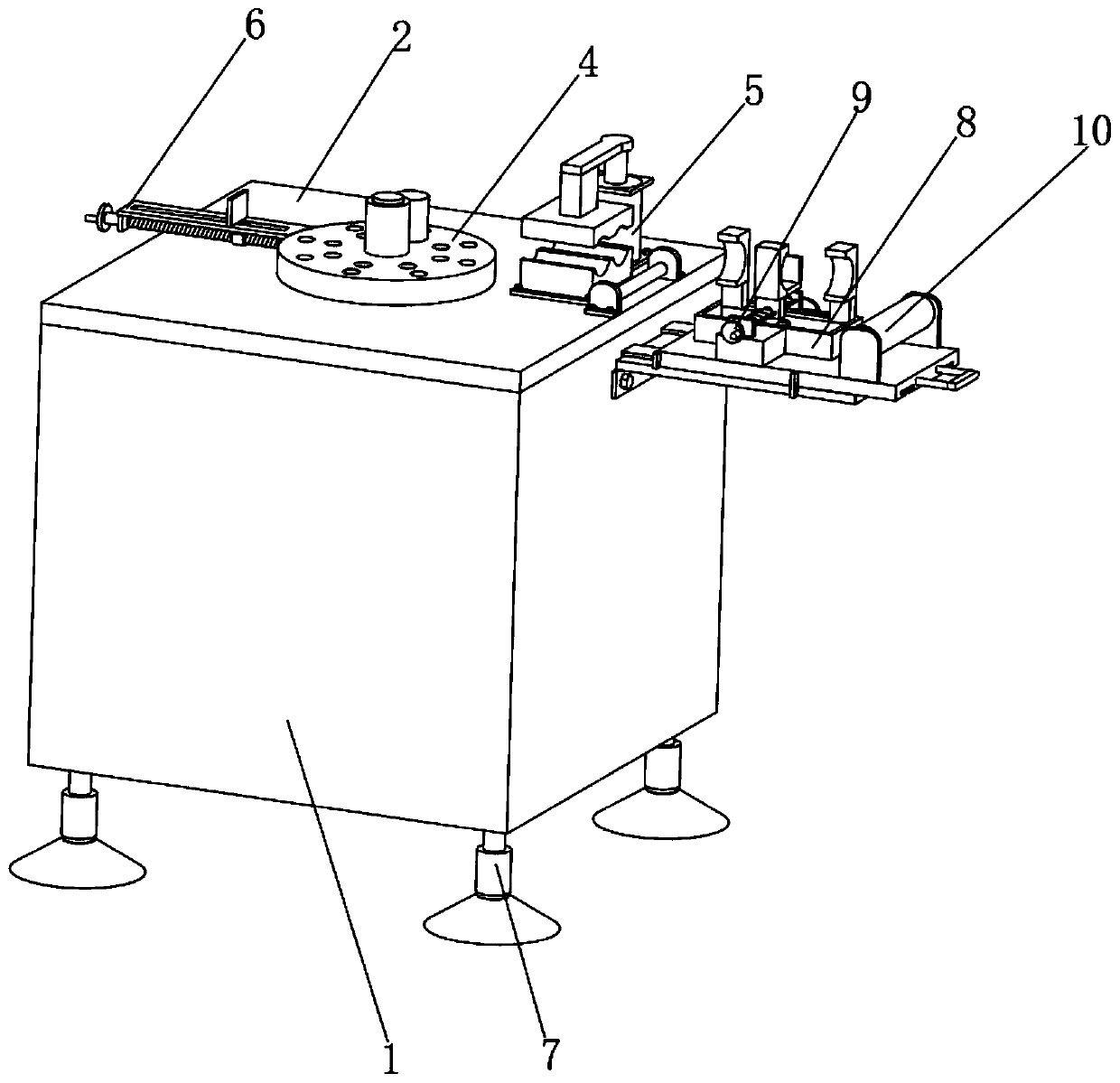
[0045] Embodiment one, with reference to figure 1 , figure 2 and image 3 , a steel bar bending equipment for construction engineering, comprising a housing 1, characterized in that the top of the housing 1 is provided with a workbench 2, the inside of the housing 1 is provided with a driving mechanism 3, and the output end of the driving mechanism 3 is provided There is a twisting mechanism 4, one side of the twisting mechanism 4 is provided with an auxiliary mechanism 8 fixedly connected with the housing 1, and the bottom of the housing 1 is provided with an adjusting mechanism 7, wherein,

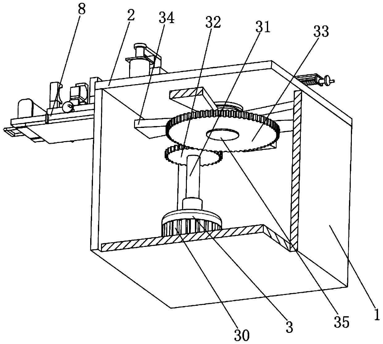
[0046] The driving mechanism 3 includes a driving motor 30 fixedly connected to the bottom of the housing 1, the free end of the output shaft of the driving motor 30 is fixedly connected with a connecting shaft 31, the side of the connecting shaft 31 is fixedly connected with a driving gear 32, and one side of the driving gear 32 is provided There is a transmission shaft 35, the surfa...

Embodiment 2

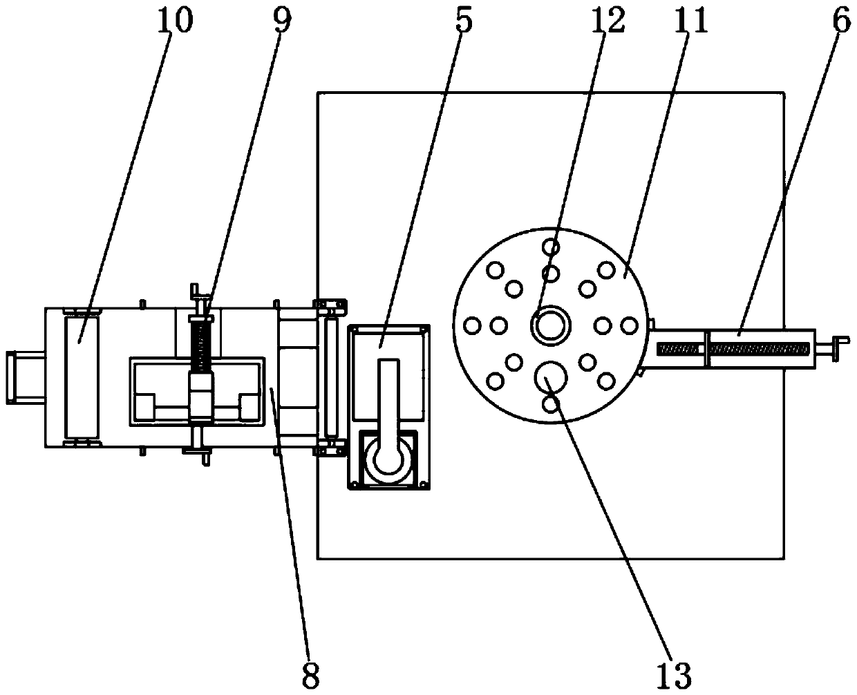
[0069] Example 2, please refer to Figure 10 According to the above-mentioned embodiment, when the steel bar is bent on the workbench 2, when the steel bar enters the guide pin 12 and the auxiliary pin 13 of the turntable 11, after the driving mechanism 3 drives the turntable 11 to rotate, the first bending of the steel bar is completed. At this time, another auxiliary pin 13 is inserted in the turntable 11, and then the driving mechanism 3 rotates again, the auxiliary pin 13 further limits the reinforcement, the reinforcement rotates along the auxiliary pin 13, and the reinforcement is formed into an N shape or an S shape. The use of auxiliary pin 13 makes it convenient for the steel bar to be formed into different shapes.

Embodiment 3

[0070] Example three, please refer to Figure 11 and Figure 12 According to the above-mentioned embodiment, the upper die 53 is rotationally connected with the transmission plate 54, the positioning bolt 57 is threadedly connected between the upper die 53 and the transmission plate 54, the lower die 52 and the upper die 53 are slidingly connected by a guide pin 56, and the upper die The inside of 53 is rotatably connected with an adjusting screw 59, and the opposite surfaces of the lower dies 52 and 53 (not shown on the original surface) are provided with square clamping blocks 510, one of which is threadedly connected to the adjusting screw 59, and the other The square clamping block 510 is slidingly connected with the lower mold 52, and the two square clamping blocks 510 are respectively slidingly connected with the adjusting connecting rod 58. When processing the square steel bar, only the positioning bolt 57 needs to be rotated in the opposite direction, and the positioni...


PUM


Abstract

The invention relates to the technical field of steel bar bending machines, in particular to steel bar bending equipment and method for building engineering. The steel bar bending equipment for building engineering comprises a shell, wherein a workbench is arranged at the top of the shell, a driving mechanism is arranged inside the shell, a torsion mechanism is arranged at the output end of the driving mechanism, an auxiliary mechanism fixedly connected with the shell is arranged on one side of the torsion mechanism, and an adjusting mechanism is arranged at the bottom of the shell. A drivinggear is used as a small gear to drive a driven gear to rotate as a large gear, the rotating force is small, the torsion force of a driving motor is reduced, the driving motor is prevented from being burnt due to excessive load, high-efficiency bending transmission can be realized by using the motor with lower power, and the driving motor is protected.

Description

technical field [0001] The invention relates to the technical field of steel bar bending machines, in particular to a steel bar bending equipment and method for construction engineering. Background technique [0002] Rebar bending machine, one of the rebar processing machinery. The working mechanism is a horizontal working disk that rotates on a vertical axis. The steel bar is placed at the dotted line in the figure, the supporting pin is fixed on the machine tool, the center pin and the bending pin are mounted on the working disk, and the disk rotates. When bending the steel bars, in order to bend steel bars of various diameters, there are several holes on the working plate for inserting and pressing the bending pins, and the center pins of different diameters can also be replaced accordingly. [0003] When the existing steel bar bending machine is in use, the steel bar is usually directly placed on the disc, and the rotation of the pivot pin is used to force it to rotate ...

Claims


Application Information

Patent Timeline
Patent Type & Authority Applications(China)
IPC IPC(8): B21F1/00
CPCB21F1/004
Inventor 刘丽段芳利何宏昌
Owner 刘丽
Why Eureka
Try Eureka