
A Robust and Fast UAV Photogrammetry Mark Detection and Localization Method

A photogrammetry and mark detection technology, applied in image analysis, image enhancement, instruments, etc., can solve the problems of low mark positioning accuracy, low computational efficiency, and high computational complexity, achieve the advantages of detection effectiveness and reliability, overcome the The effect of blurred image and high calculation accuracy

Active Publication Date: 2021-10-08
CENT SOUTH UNIV
View PDF0 Cites 0 Cited by
  • Summary
  • Abstract
  • Description
  • Claims
  • Application Information

AI Technical Summary

Problems solved by technology

[0005] Harris corner detection is the most general corner detection method, but its defect is that it can not only detect cross-shaped corners, but also detect other types of corners such as sharp corners, and cannot achieve a single screening, so it will seriously affect Detection effectiveness and reliability of UAV survey marks
In addition, the computer vision library OpenCV provides a typical cross-shaped mark detection method, which detects corner coordinates by segmenting black and white rectangular grids and using their edge features; Wang et al. also proposed a fitting However, both methods are based on image edge features, which are easily affected by image noise, image blur and other factors, resulting in low accuracy of logo positioning
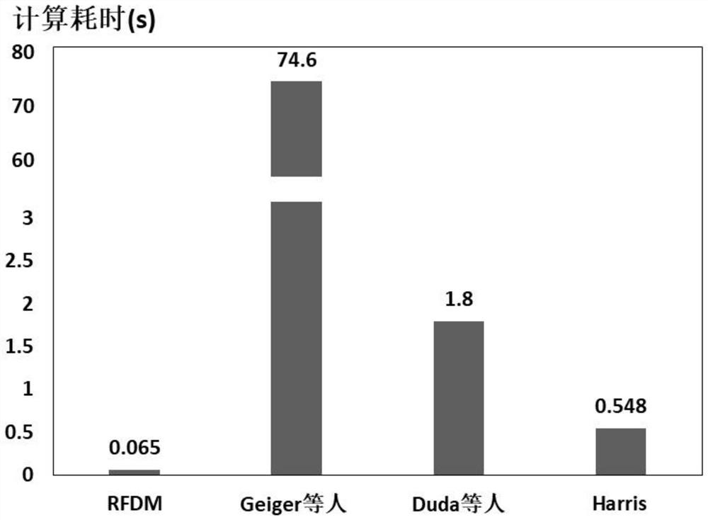
Geiger et al. proposed a method based on template matching for initial detection, and achieved good experimental results, but this method is a search method based on a sliding window, which has high computational complexity, so the computational efficiency is low, and it is not practical. sex

Method used


Image

  • A Robust and Fast UAV Photogrammetry Mark Detection and Localization Method
  • A Robust and Fast UAV Photogrammetry Mark Detection and Localization Method
  • A Robust and Fast UAV Photogrammetry Mark Detection and Localization Method

Examples


Embodiment Construction

[0053] The following will clearly and completely describe the technical solutions in the embodiments of the present invention with reference to the accompanying drawings in the embodiments of the present invention. Obviously, the described embodiments are only some, not all, embodiments of the present invention. Based on the embodiments of the present invention, all other embodiments obtained by persons of ordinary skill in the art without making creative efforts belong to the protection scope of the present invention.

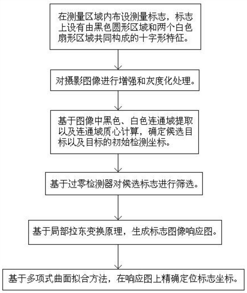
[0054] see figure 1 , a robust and fast UAV photogrammetry mark detection and positioning method, including the following steps:

[0055] Step 1. Set up signs in the measurement area;

[0056] see figure 2 , the background of the measurement mark is white and includes a black circular area and two 90° white fan-shaped areas of the same size set in the black circular area. The centers of the three areas coincide and the two white fan-shaped areas are set at ...


PUM


Abstract

The invention provides a robust and fast UAV photogrammetry mark detection and positioning method. First, the photographic image is enhanced and grayscaled, and then the centroid coordinates of each pair of black connected domains and white connected domains in the image are compared. , when the distance between the two does not exceed the set pixel threshold, the area is considered as a candidate target area and the centroid coordinates of the white connected domain are used as the initial detection coordinates of the candidate logo, and then the zero-crossing detector is used to detect the crossing in the neighborhood of the candidate logo. If and only when the number of zero-crossing points is 4, keep the candidate target, otherwise delete the candidate target, and finally perform polynomial surface fitting on the gray intensity response map of the sign image generated based on the local Radon transform, and iteratively solve the proposed The precise coordinates of the maximum point of the combined surface, that is, the high-precision coordinates of the measurement mark. The invention has strong anti-interference ability, improves calculation efficiency and mark positioning accuracy, and is suitable for processing large-resolution images.

Description

technical field [0001] The invention belongs to the technical field of engineering surveying, and in particular relates to a robust and fast method for detecting and locating marks of unmanned aerial vehicle photogrammetry. Background technique [0002] With the gradual maturity of UAV hardware technology and computer vision algorithms, photogrammetry methods based on UAV platforms have been widely used in the field of engineering surveying. Among them, the use of UAV photogrammetry marks to determine the coordinate reference frame of the photogrammetry 3D model is one of the main research contents of the photogrammetry technology based on the UAV platform, and the research has high accuracy, high precision positioning and no human intervention. The method of automatic detection and positioning of measurement marks is very important for improving the degree of automation and measurement accuracy of photogrammetry technology. However, due to the complex natural environment, ...

Claims


Application Information

Patent Timeline
Patent Type & Authority Patents(China)
IPC IPC(8): G06T7/136G06T7/187G06T7/90
CPCG06T2207/10004G06T2207/10024G06T7/136G06T7/187G06T7/90
Inventor 戴吾蛟邢磊
Owner CENT SOUTH UNIV
Learn More