
Support seat adjusting method and support seat adjusting device

An adjustment method and technology of an adjustment device, which are applied in the directions of supporting machines, machines/brackets, instruments, etc., can solve the problems of low radar adjustment efficiency, and achieve improved feasibility and efficiency, low requirements for adjustment conditions, and improved stability. Effect

Active Publication Date: 2020-05-12
UBTECH ROBOTICS CORP LTD
View PDF4 Cites 0 Cited by
  • Summary
  • Abstract
  • Description
  • Claims
  • Application Information

AI Technical Summary

Problems solved by technology

[0004] One purpose of the present application is to provide a method for adjusting the support seat, aiming to solve the problem of low radar adjustment efficiency in the prior art

Method used


Image

  • Support seat adjusting method and support seat adjusting device
  • Support seat adjusting method and support seat adjusting device
  • Support seat adjusting method and support seat adjusting device

Examples


specific Embodiment approach

[0082] Furthermore, as another specific implementation of the method for adjusting the support seat provided in this application, turning the first threaded member 33 to rotate specifically includes: judging the direction in which the first adjusting member 31 needs to move, if the first adjusting member 31 needs to move toward If the deeper part of the first adjusting groove 21 moves, then the first screw member 33 is screwed in the first direction of rotation. The opposite second rotational direction turns the first threaded part 33 .

[0083] Further, as another specific embodiment of the method for adjusting the support seat provided in the present application, the base 1 is provided with a second slide groove 12 opposite to the second adjustment groove 22; the inner wall of the second slide groove 12 is provided with a second screw thread The through hole 14, the second adjustment drive mechanism includes a second slider 42 connected with the second adjustment member 41 a...


PUM


Abstract

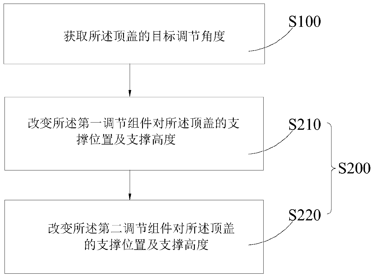
The invention discloses a support seat adjusting. The support seat adjusting method comprises the steps of acquiring a target adjusting angle of a top cover; and 2, adjusting a first adjusting assembly and a second adjusting assembly according to the target adjusting angle so as to adjust the orientation of the top cover to the target adjusting angle. The relative position between the top cover and a base is changed through the first adjusting assembly and the second adjusting assembly, namely the adjustment is achieved by two supporting points of the first adjusting assembly and the second adjusting assembly, so that the angle of the top cover of a support seat is changed. Compared with a three-point adjusting mode, the adjustment parameters are reduced, so that the adjustment and the structural stability are further improved; and with the two-point adjustment, only two variables need to be considered, and only two adjusting points need to be operated, therefore, the requirement on adjustment conditions is lower, and the feasibility and the efficiency are effectively improved.

Description

technical field [0001] The present application relates to the field of radar installation and adjustment, and in particular to a support base adjustment method and a support base adjustment device. Background technique [0002] Two-dimensional laser radar is a non-contact distance detection device, which obtains the coordinates of the target by emitting pulsed laser light in a fixed angle range and detecting the return light signal. Due to existing assembly and machining defects, there is an angle between the outgoing pulse laser and the reference plane of the laser radar. If the angle is greater than ±1°, it will seriously affect the accuracy of the distance information of the detected target, resulting in an increase in the target distance estimation deviation. Even if the target is lost, it will seriously affect the navigation accuracy and anti-collision prediction, and bring safety hazards to the mechanical device equipped with this equipment. [0003] In order to reali...

Claims


Application Information

Patent Timeline
IPC IPC(8): F16M13/02F16M11/24F16M11/04G01S7/481
CPCF16M13/02F16M11/24F16M11/043G01S7/481
Inventor 赵永进周礼兵余文华覃甲林熊友军
Owner UBTECH ROBOTICS CORP LTD
Learn More