
Swing type solar panel driving mechanism

A technology for solar panels and driving mechanisms, applied in electromechanical devices, mechanical equipment, electric components, etc., can solve the problems of complex conductive ring structure, affecting the performance of the whole star, low reliability, etc., and achieve high output torque and small backlash. , the effect of improving reliability

Active Publication Date: 2020-05-12
BEIJING INST OF CONTROL ENG
View PDF9 Cites 2 Cited by
  • Summary
  • Abstract
  • Description
  • Claims
  • Application Information

AI Technical Summary

Problems solved by technology

There is friction and wear in the conductive slip ring, the life is low, and the cost is high; in the existing solar panel drive mechanism, the ring-brush friction pair of the disc ring or the column ring is used to realize power and signal transmission
The conductive ring has the problems of complex structure, high cost, low reliability and heavy weight
In addition, the conductive ring generally needs to use a non-metallic insulating structure as a supporting structure, resulting in heavy weight and low rigidity, which affects the performance of the entire star

Method used


Image

  • Swing type solar panel driving mechanism
  • Swing type solar panel driving mechanism
  • Swing type solar panel driving mechanism

Examples


Embodiment Construction

[0021] The present invention will be further elaborated below in conjunction with embodiment.

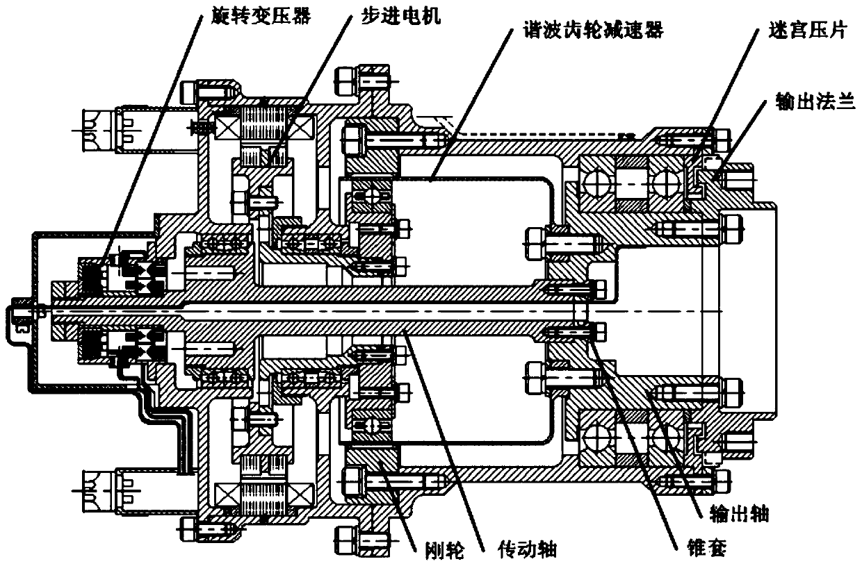
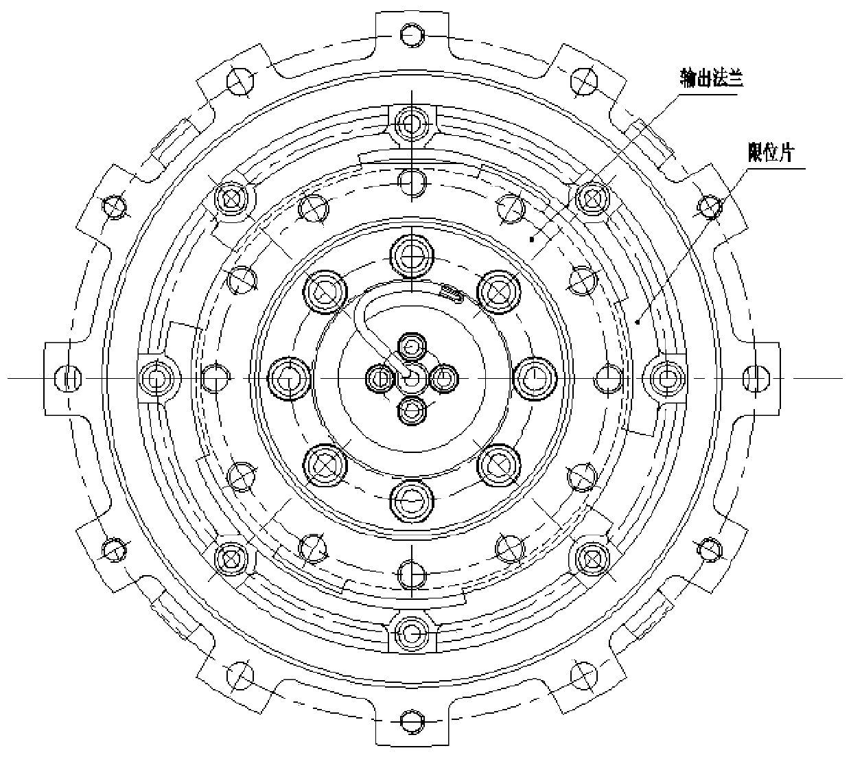
[0022] Such as figure 1 As shown, the present invention provides a swing type solar panel drive mechanism, which drive mechanism includes a rotary transformer, a stepper motor, a harmonic gear, an output shaft, a housing, a torsion cable; the fixing of the stepper motor and the harmonic gear partially mounted on the housing, where:

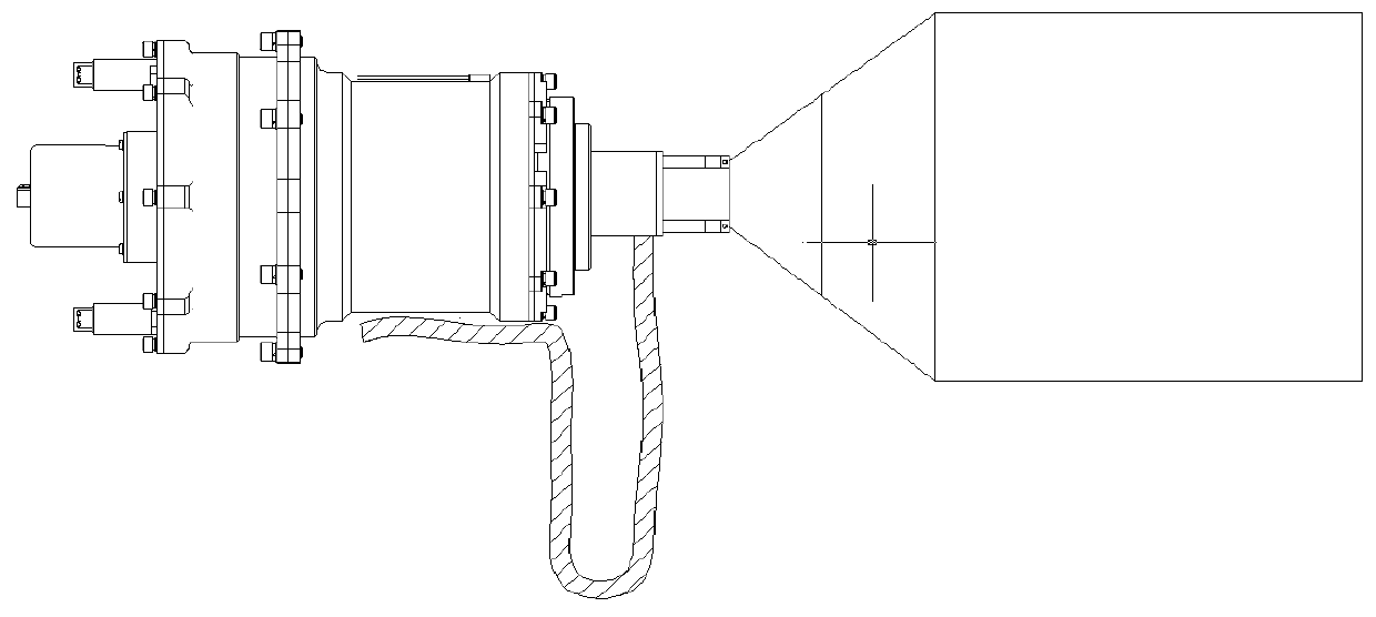
[0023] The stepper motor is connected to the harmonic gear, which is used to decelerate the speed of the stepper motor and transmit the torque of the stepper motor shaft to the output shaft, which is used to connect the external solar panel to drive the solar panel to swing ; The resolver is used to measure the rotation angle of the output shaft; one end of the torsion cable is connected to the external actuator, and the other end is connected to the casing of the driving mechanism. The torsion cable is used to replace the disc ring to complete power ...


PUM


Abstract

The invention relates to a swing type solar panel driving mechanism. The structure of the swing type solar panel driving mechanism comprises a rotary transformer, a stepping motor, a harmonic gear, anoutput shaft, a shell and a torsional pendulum cable; the fixed parts of the stepping motor and the harmonic gear are mounted on the shell; the stepping motor is connected with the harmonic gear, theharmonic gear is used for reducing the rotating speed of the stepping motor and transmitting the torque of a rotating shaft of the stepping motor to the output shaft, and the output shaft is used forbeing connected with an external solar panel and driving the solar panel to swing; the rotary transformer is used for measuring the rotation angle of the output shaft; and one end of the torsional pendulum cable is connected to an external actuating mechanism, and the other end of the torsional pendulum cable is connected to the shell of the drive mechanism. According to the swing type solar panel driving mechanism, a method for realizing electric signal transmission by replacing a slip ring with the torsional pendulum cable is adopted, and low weight, high rigidity, high reliability and longservice life are realized.

Description

technical field [0001] The invention relates to a swing-type solar sail panel drive mechanism, which belongs to the technical field of space pointing and tracking mechanisms. Background technique [0002] The driving mechanism of the solar panel generally uses a conductive slip ring to realize the electrical connection between the rotating solar wing and the star. There is friction and wear in the conductive slip ring, the life is low, and the cost is high; in the existing solar panel drive mechanism, the ring-brush friction pair of the disk ring or the column ring is used to realize power and signal transmission. The conductive ring has the problems of complex structure, high cost, low reliability and heavy weight. In addition, the conductive ring generally needs to use a non-metallic insulating structure as a supporting structure, resulting in heavy weight and low rigidity, which affects the performance of the entire star. Contents of the invention [0003] The technic...

Claims


Application Information

Patent Timeline
Patent Type & Authority Applications(China)
IPC IPC(8): F16H49/00F16H57/023H02K7/116
CPCF16H49/001F16H57/023H02K7/116
Inventor 王斌袁军周剑敏吴纾婕邵超李根臧晓林朱林林高卫青
Owner BEIJING INST OF CONTROL ENG
Learn More