
Follow-up tilting-head type big-tapered wire cutting device

A technology of wire cutting and large taper, which is applied in the field of follow-up swing head type large taper wire cutting device, which can solve the problems of increasing the weight of the upper cantilever cantilever, changing the tension of the electrode wire, and easily reducing the processing accuracy, etc., to achieve weight reduction , Improve the effect of accuracy, stability and reliability

Active Publication Date: 2020-05-12
CHANGZHOU INST OF TECH
View PDF7 Cites 8 Cited by
  • Summary
  • Abstract
  • Description
  • Claims
  • Application Information

AI Technical Summary

Problems solved by technology

[0006] 1. In the patent application 201810493752.4, only the taper processing of the wire guide wheel at the front of the cantilever is considered, but the wire electrode moves continuously during the wire cutting process, and other wire guide mechanisms need to be used to achieve the stability of the wire electrode. After the front wire guide wheel is deflected, its angle deviates from that of other wire guide wheels, which will easily cause the electrode wire to slip during processing and cause processing failures;
[0007] 2. The yaw action of the wire guide wheel at the front of the cantilever will not only tilt the electrode wire between the upper and lower cantilever, but also cause a certain change in the length of the electrode wire, which will lead to a change in the tension of the electrode wire, so it needs to be considered Design a suitable tensioning device to accommodate the smooth transition of the tilting movement of the electrode wire;
[0008] 3. Wire cutting complex shapes is a process of multi-axis linkage. The UV axis of the wire cutting machine tool is mainly used to control the movement of the upper cantilever (upper mechanical arm) relative to the lower cantilever, so that the electrode wire between the upper and lower cantilever tilts. The cutting machine tool installs the Z-axis mechanism on the upper cantilever (such as the above two patent applications), which increases the weight of the cantilever side of the upper cantilever. Therefore, the structural strength and stability of the UV-axis drive mechanism are required to be higher, which is easy to cause the upper cantilever Vibration can easily reduce machining accuracy

Method used


Image

  • Follow-up tilting-head type big-tapered wire cutting device
  • Follow-up tilting-head type big-tapered wire cutting device
  • Follow-up tilting-head type big-tapered wire cutting device

Examples


Embodiment

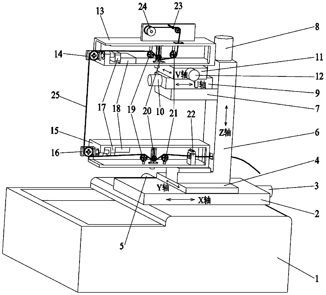
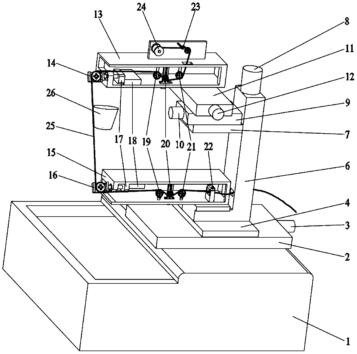
[0042] to combine figure 1 with figure 2 As shown, a follow-up swing head type large-taper wire cutting device in this embodiment includes a bed 1, an X-axis table 2, an X-axis driving mechanism 3, a Y-axis table 4, a Y-axis driving mechanism 5, and a spindle 6. Z-axis table 7, Z-axis drive mechanism 8, U-axis table 9, U-axis drive mechanism 10, V-axis table 11, V-axis drive mechanism 12, upper mechanical arm 13, upper swing head 14, lower mechanical The arm 15, the lower swing head 16, the electrode wire 25 and the wire feeding mechanism, the bed 1 is used to support the whole wire cutting device, the X-axis workbench 2 is installed on the bed 1 through the X-axis drive mechanism 3, and the Y-axis workbench 4 passes through The Y-axis driving mechanism 5 is installed on the X-axis table 2, the main shaft 6 is vertically installed on the Y-axis table 4, the lower mechanical arm 15 is fixedly installed on the lower end of the main shaft 6 or on the Y-axis table 4, and the low...


PUM


Abstract

The invention discloses a follow-up tilting-head type big-tapered wire cutting device, and belongs to the field of spark cutting equipment. According to the big-tapered wire cutting device provided bythe invention, tilting heads on an upper mechanical arm and a lower mechanical arm are follow-up adjusted by adopting the matching of tilting head rotating mechanisms and cutting tapers; universal wire guiding wheels and the corresponding upper and lower tilting heads are matched, and tensioning mechanisms between the universal wire guide wheels and directional wire guide wheels are combined fortransition, so that an electrode wire is smooth in transition, the problem that the electrode wire falls down during big-tapered cutting is effectively prevented, and an electrode wire follow-up deflection position is controlled accurately. Meanwhile, on the basis of building an XYZ three-axis numerical control device on a lathe bed, a U axis and a V axis are arranged on a Z-axis working table, and the upper mechanical arm is arranged on a V-axis working table, so that the weight of the upper mechanical arm is reduced, the operation stability and the reliability of a U-axis drive mechanism anda V-axis drive mechanism are improved favorably, the vibration of the upper mechanical arm in the processing process is reduced, the wire cutting processing accuracy is improved, and the service lifeof the big-tapered wire cutting device is prolonged.

Description

technical field [0001] The invention relates to a wire electric discharge cutting device, in particular to a follow-up swing head type large taper wire cutting device. Background technique [0002] Wire EDM equipment is widely used in mechanical processing. Its basic working principle is to use continuously moving thin electrode wire (wire) as an electrode to perform pulse spark amplification on the workpiece to remove metal and cut it into shape. It is mainly used for processing various Workpieces with complex shapes and fine details, such as various micro-hole grooves, narrow slots and curves, etc. Because wire cutting has the advantages of small machining allowance, high cutting precision and low manufacturing cost, it has been widely used in production. [0003] As the requirements for processed parts are getting higher and higher, the taper processing requirements are also put forward for wire cutting, that is, wire cutting is required to be able to cut parts with tape...

Claims


Application Information

Patent Timeline
Patent Type & Authority Applications(China)
IPC IPC(8): B23H7/02B23H7/30B23H7/10
CPCB23H7/02B23H7/30B23H7/105B23H7/104
Inventor 徐波余辉白建会
Owner CHANGZHOU INST OF TECH
Learn More