
Strong mixing reactor

A technology for mixing reactors and reactors, which is applied in the field of reactors, can solve the problems of increasing the complexity of the process flow, the structure of the reactors, the loss of stirring paddles, etc., so as to improve the efficiency of the reactors, improve the space utilization rate, and improve the mixing of each phase. uniform effect

Pending Publication Date: 2020-05-12
TSINGHUA UNIV
View PDF3 Cites 1 Cited by
  • Summary
  • Abstract
  • Description
  • Claims
  • Application Information

AI Technical Summary

Problems solved by technology

However, the stirred tank reactor has several obvious disadvantages: 1) There are rotating parts of the stirring paddle in the kettle, and the requirements for sealing are more stringent; 2) The stirring paddle reduces the volume of the reactor where heat exchange components can be installed; 3) The rotation loss of the stirring paddle High power, especially for large-scale process problems are more prominent
For gas-liquid systems with low demand for liquid-liquid, liquid-solid and reactive gases, the operating gas velocity can be matched by introducing inert gas, but the introduction of inert gas increases the complexity of the process and also requires the reactor to have Good gas-liquid separation ability
[0004] Patent CN107626268A discloses a kind of liquid-liquid two-phase reactor and patent CN208679154U discloses a kind of continuous reactor matching automatic continuous mixing and liquid-liquid separation device, all utilize the stirrer mixing material that is arranged on the central axis of the reactor; patent CN208661109U has announced a kind of Venturi jet loop esterification reactor, and its inlet material utilizes Venturi mixed-flow nozzle to promote mixing, but the fluid mixing in the reactor still relies on complicated stirring system
These patents all use the mixer to mix the materials, and the reactor structure is relatively complicated.

Method used


Image

  • Strong mixing reactor
  • Strong mixing reactor
  • Strong mixing reactor

Examples


Embodiment 1

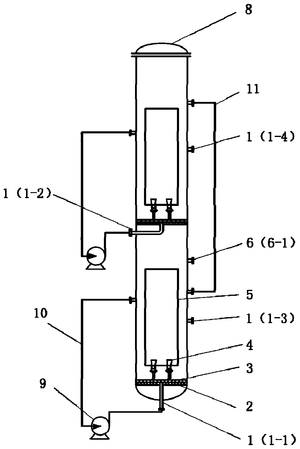
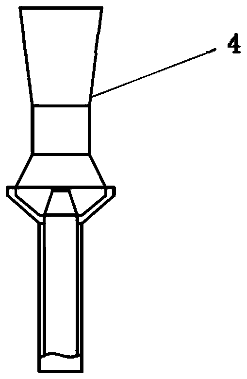
[0036] figure 1 and figure 2It is a schematic diagram of the implementation structure of a liquid-liquid multi-stage strong mixing reactor. In the reactor of this embodiment, the reactor is two stages, and the reactor is the first stage and the second stage successively from top to bottom; The reactor comprises a reactor liquid inlet (1), a liquid outlet (6), and the reactor Bed body (8), inner sleeve (5), circulation pipeline (10) and circulation pump (9) installed on the periphery of the reactor. The substrates (2) of the reactors at all levels are arranged with liquid distributors (3), and the liquid distributors (3) are equipped with single or multiple Venturi mixed flow nozzles (4); the liquid distributors (3) are controlled by the liquid distributors It is composed of one or more liquid distribution pipes (12); one end of the liquid distribution pipe is connected with the hole on the main pipe of the liquid distributor, and the other end is connected with the Venturi ...

Embodiment 2

[0043] Image 6 It is a schematic diagram of the implementation structure of the liquid-solid and liquid-liquid-solid system multi-stage strong mixing reactor. In the reactor of this embodiment, the reactor has two stages, and the reactor is the first stage and the second stage from top to bottom; The same; in addition, the circulating liquid formed in the inner sleeve and between the annulus drives the solid catalyst particles to evenly suspend. The liquid-solid fluid in each stage reactor is separated from solid and liquid through the baffle plate (13) on the upper part of the reactor; part of the clarified liquid enters the circulation pipeline (10) of the stage, and part of it passes through the liquid outlet (6) or stage The intermediate overflow pipe flows out of the reactor at this stage; the solid catalyst returns to the circulation area of ​​the reactor at this stage through the arcuate through hole formed by the baffle plate and the reactor bed due to the gravity se...

Embodiment 3

[0047] Figure 8 It is a schematic diagram of the implementation structure of the gas-liquid and gas-liquid-liquid system multi-stage strongly mixed parallel flow reactor. In the reactor of this embodiment, the reactor is two stages, and the reactor is the first stage and the second stage successively from top to bottom; the reactor comprises a reactor liquid inlet (1), a gas inlet (15), and a liquid outlet (6), a reactor bed body (8), an inner sleeve (5), a circulation pipeline (10) and a circulation pump (9) installed on the periphery of the reactor. Liquid distributors (3) and gas distributors (16) are arranged at the bottom of the reactors at all levels.

[0048] In the reactor of this embodiment, the liquid circulation in the stage of each stage reactor is the same as that of Embodiment 1; in addition, the bubbles flowing out from the gas distributor (16) further promote the internal circulation flow formed in the inner sleeve and between the annulus , so as to achieve ...


PUM


Abstract

A strong mixing reactor relates to a strong mixing reactor suitable for liquid-liquid, liquid-solid and gas-liquid, gas-liquid-solid multiphase reaction processes with relatively low gas quantity. Thereactor is mainly and technically characterized in that energy is carried through liquid external circulation, and the circulation flow in a fluid is amplified in a mode of combined use of a venturimixed flow nozzle and an inner sleeve, so that each phase in the reactor is quickly, uniformly and strongly mixed; through the flow amplification effect of the coupling nozzle and the inner sleeve, mechanical stirring or gas carrying energy is replaced, and strong mixing of multi-phase fluids can be well achieved; and the reactor has the advantages of simple structure, uniform mixing of each phase, uniform particle suspension, high reactor efficiency and large fluid circulation flow in the reactor. According to the reactor, the effect of a multi-kettle series reactor is achieved through a simple structure, continuous operation of multiple reaction steps is achieved in a single reaction tower, the size of the reactor is reduced under the same reaction conversion rate, and the efficiency ofthe reactor is improved.

Description

technical field [0001] The invention relates to a reactor suitable for liquid-liquid, liquid-solid, gas-liquid and gas-liquid-solid multiphase reaction systems, in particular to a multi-stage strong mixing reactor. Background technique [0002] Liquid-liquid, liquid-solid, gas-liquid and gas-liquid-solid multiphase reaction systems are widely used in chemical, energy, environment, biochemical and other fields. Among these reaction systems, the stirred tank reactor has the most flexible application. The stirred tank adopts external mechanical stirring, and its liquid phase is violently turbulent, with good mixing characteristics and interphase mass transfer rate; at the same time, it can better ensure the uniform suspension of solid phase catalyst particles, thereby ensuring a higher utilization rate of the solid catalyst. However, the stirred tank reactor has several obvious disadvantages: 1) There are rotating parts of the stirring paddle in the kettle, and the requirement...

Claims


Application Information

Patent Timeline
IPC IPC(8): B01J19/00B01J4/00B01J19/24B01F5/04
CPCB01J19/006B01J19/0053B01J4/002B01J4/001B01J19/24B01J19/249B01F25/31252B01F25/312
Inventor 王铁峰蓝晓程张华海
Owner TSINGHUA UNIV
Learn More