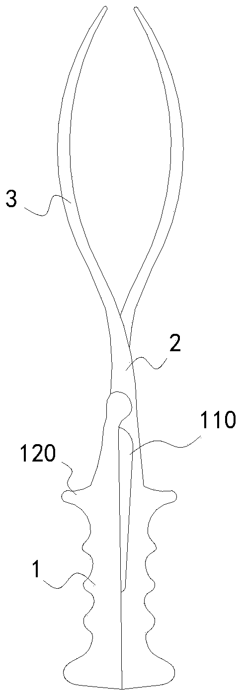
Obstetric forceps
A technology of forceps handle and forceps arm, which is applied in obstetrics and gynecology instruments, and can solve problems such as threats to the life and health of fetuses, intracranial hemorrhage, and fetal cheek injuries
- Summary
- Abstract
- Description
- Claims
- Application Information
AI Technical Summary
Problems solved by technology
Method used
Image
Examples
Embodiment 1
[0036] Forceps, including a pair of forceps handles 1, the forceps handle 1 is connected with the forceps arm 2, the forceps arm 2 is connected with the forceps blade 3, and the inner side of one forceps handle 1 in the pair of forceps handles 1 is provided with a groove that is concave to the inside of the forceps handle 1 The clamping sensing groove 110 is used for the finger to sense the clamping force of the forceps after the finger is inserted into the clamping sensing groove 110 .
[0037] After the pliers blade 3 is put in place, hold the pliers handle 1 with one hand, hook the handle 120 on both sides of the pliers handle 1 with the index finger and ring finger of the other hand, and extend the middle finger into the clamping and sensing pliers, which is very convenient. The clamping force of the obstetric forceps can be sensed by the clamping pressure of the two forceps handles 1 of the middle finger.
[0038] When not in use, after the two pliers handles 1 are closed...
Embodiment 2
[0040] The difference from Embodiment 1 is that the above-mentioned pair of pliers handles 1 opposite sides are provided with clamping sensing grooves 110 recessed inwardly towards the inner side of the pliers handle 1, that is, the clamping sensing grooves 110 here are composed of two respectively arranged on the two sides. Symmetrical grooves on the two forceps handles 1 are combined to form, and the clamping sensing groove 110 is used for fingers to be inserted into the clamping sensing groove 110 after the two forceps handles 1 are closed so that the fingers sense the clamping force of forceps.
Embodiment 3
[0042] On the basis of Embodiment 1 or 2, a protective pad 4 made of elastic material is arranged in the above-mentioned clamping sensing groove 110, and the elastic material can be rubber, silica gel, sponge or cotton cloth and the like.
[0043] Preferably, the protective pad 4 is detachably connected to the pliers handle 1 . The detachable connection here can be to put the protective pad 4 in the clamping sensing groove 110, or wrap it on the position of the clamping sensing groove 110 corresponding to the pliers handle 1, or stick it on the clamping sensing groove by bonding 110 and so on.
[0044] like Figure 8 Wrapped in the position of the clamping sensing groove 110 corresponding to the clamp handle 1, that is, the protective pad 4 is a cylindrical sleeve sleeve on the clamp handle 1, and a preset part is provided on the side of the cylindrical protective pad 4 for the pull handle 120 to protrude. Holes 410 are left.
PUM
 Abstract
Description
Claims
Application Information
 - R&D Engineer
- R&D Manager
- IP Professional
- Industry Leading Data Capabilities
- Powerful AI technology
- Patent DNA Extraction
Browse by: Latest US Patents, China's latest patents, Technical Efficacy Thesaurus, Application Domain, Technology Topic, Popular Technical Reports.
© 2024 PatSnap. All rights reserved.Legal|Privacy policy|Modern Slavery Act Transparency Statement|Sitemap|About US| Contact US: help@patsnap.com


