Eureka AIR delivers breakthrough ideas for toughest innovation challenges, trusted by R&D personnel around the world.

White LED light source with infrared band added in spectrum

A technology of LED light source and infrared band, applied in the field of white light LED light source, can solve the problems of insufficiency and lack of infrared band, and achieve the effect of no light spot and good uniformity of color temperature

Inactive Publication Date: 2020-05-08
北京宇极芯光光电技术有限公司 +2
View PDF4 Cites 0 Cited by
  • Summary
  • Abstract
  • Description
  • Claims
  • Application Information

AI Technical Summary

Problems solved by technology

[0009] However, compared with sunlight, the above-mentioned kinds of white light all lack infrared bands.
It cannot meet the special needs of plant lighting color detection, video surveillance, etc. that require the addition of infrared bands

Method used


Image

  • White LED light source with infrared band added in spectrum
  • White LED light source with infrared band added in spectrum
  • White LED light source with infrared band added in spectrum

Examples


Embodiment 1

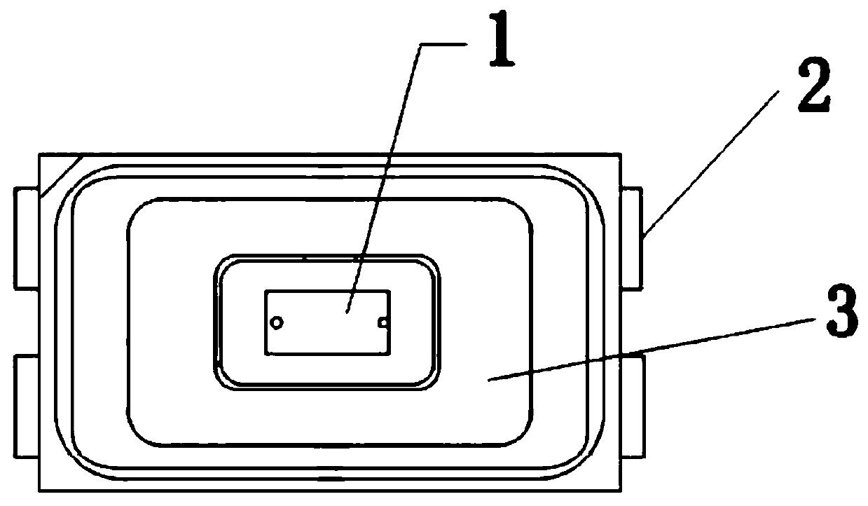
[0033] Such as figure 1 As shown, the white light SMD LED lamp bead of this embodiment includes an LED chip 1 , two electrodes 2 and an LED bracket 3 , and the two electrodes are respectively located at both ends of the LED bracket 3 for leading out the positive and negative poles of the LED chip 1 .

[0034] First, fix the chip 1 (a chip with a peak wavelength of 405nm in this embodiment) on the LED bracket 3, and connect the two ends of the chip to the two pole pieces at the bottom of the substrate through gold wires to conduct with the two electrodes 2.

[0035] Then, a certain ratio is prepared to contain infrared, red, green, and blue four-color fluorescent powder (infrared fluorescent powder (Y, Gd) of this embodiment) 3 Ga 5 o 12 : Cr, red phosphor: CaAlSi(ON )3 :Eu, green phosphor: β-SiAlON:Eu, blue phosphor: (Sr,Ba) 10 (PO 4 ) 6 Cl 2 :Eu) mixed colloid, stirred evenly, vacuum defoaming.

[0036] Further, the mixed colloid is uniformly coated on the LED chip, a...

Embodiment 2

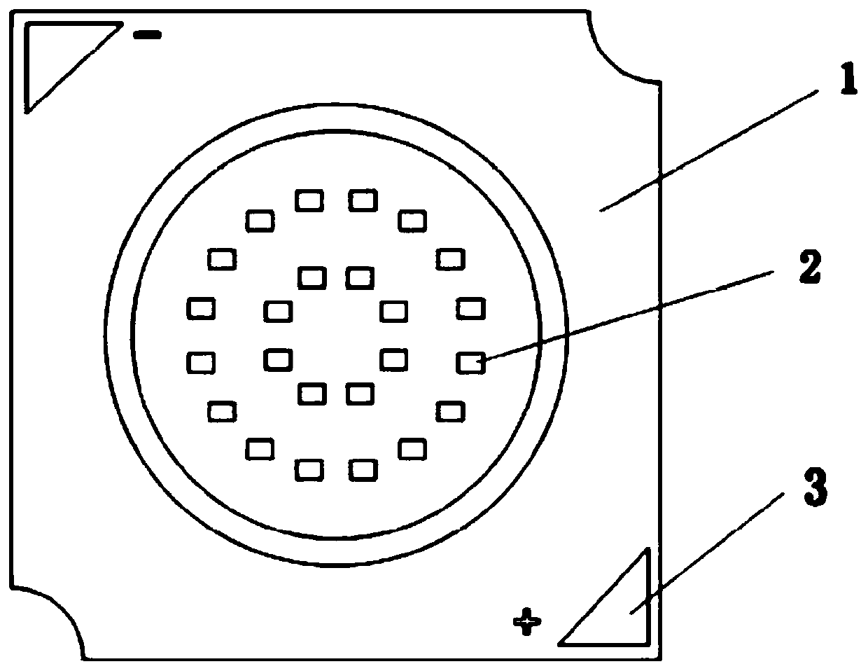
[0042] Such as image 3 As shown, the white light LED module of this embodiment includes an LED module bracket 1, an LED chip 2 and two electrodes 3, and the two electrodes are respectively located at two opposite corners of the LED module bracket 1 for leading out the positive side of the LED chip 2. negative electrode.

[0043] First, several chips 2 (chips with a peak wavelength of 405nm are used in this embodiment) are fixed on the LED module bracket 1, and the two ends of the chips are respectively connected to the two pole pieces at the bottom of the substrate through gold wires in a series-parallel manner, so as to be connected to the two electrode 3 to conduction.

[0044] Then, after damming and baking, a certain proportion is prepared to contain infrared, red, green, blue (infrared fluorescent powder in this embodiment: (Y, Gd) 3 Ga 5 o 12 : Cr, red phosphor: CaAlSi(ON )3 :Eu, green phosphor: β-SiAlON:Eu, blue phosphor: (Sr,Ba) 10 (PO 4 ) 6 Cl 2 :Eu) Mixed c...


PUM


Abstract

The invention relates to a white LED light source with an infrared band added in a spectrum. The light source is composed of an LED support, an ultraviolet or near-ultraviolet LED chip (380nm-420nm) and mixed fluorescent powder glue (infrared, red, green and blue). The light emitted by the ultraviolet or near ultraviolet LED chip is utilized to activate a fluorescent powder layer on the surface togenerate mixed white light comprising near-infrared, red, green and blue bands. According to the invention, the infrared band spectrum is supplemented, so the spectrum is closer to the solar spectrum, and the white LED light source is the best choice for an existing LED to generate high-color-rendering white light which is closest to the solar spectrum. The light source can obtain a very high color rendering index, and the generated infrared light not only can promote the growth of plants, but also can be used for other special purposes needing infrared bands. Because the infrared fluorescentpowder has higher thermal stability than an infrared chip, wavelength drift is not easy to occur in use, which cannot be realized by any other light emitting mode.

Description

technical field [0001] The invention relates to the technical field of LEDs, in particular to a white LED light source which uses infrared fluorescent powder and increases the infrared band. Background technique [0002] In today's increasingly scarce energy, compared with traditional fluorescent lamps and incandescent lamps, white LEDs, as a new type of lighting source, have significant advantages such as energy saving, environmental protection, short response time, and long life. At present, the LED industry is developing rapidly. In addition to entering the general lighting market, LED light sources have also been widely used in the professional lighting field. Among them, white LEDs are mainly used in professional fields such as photographic lighting, color detection, and plant growth. White light LED mainly has the following kinds of light emitting methods. [0003] 1. Use red, green, and blue chips to emit light and mix colors to produce white light, or use blue + ye...

Claims


Application Information

Patent Timeline
IPC IPC(8): H01L33/48H01L33/50H01L33/62
CPCH01L33/48H01L33/504H01L33/62
Inventor 黎力鲁路赵馥兴管晓笙
Owner 北京宇极芯光光电技术有限公司
Why Eureka
Eureka Blog
Learn More