Backlight device for fingerprint identification and electronic equipment

A backlight device and fingerprint recognition technology, applied in the field of communication, can solve the problems of uneven brightness and darkness of the display area of ​​the liquid crystal display device, and achieve the effect of maintaining the brightness and uniformity of light emission

Inactive Publication Date: 2020-05-08
SHENZHEN LONGLI TECH CO LTD
View PDF9 Cites 0 Cited by
  • Summary
  • Abstract
  • Description
  • Claims
  • Application Information

AI Technical Summary

Problems solved by technology

In addition, when the fingerprint identification unit 103 is placed above the backlight device, from the viewing angle of the display screen, the light transmittance of the display area where the fingerprint identification unit is placed below is compared to the light transmittance of other display areas where the fingerprint identification unit is not provided. It should be low, and the LED backlight at the bottom provides a uniform plane light source, the display area where the fingerprint identification unit is placed below is darker than other areas, and the display area of ​​the liquid crystal display device is unevenly bright and dark.

Method used


Image

  • Backlight device for fingerprint identification and electronic equipment
  • Backlight device for fingerprint identification and electronic equipment
  • Backlight device for fingerprint identification and electronic equipment

Examples


Embodiment 1

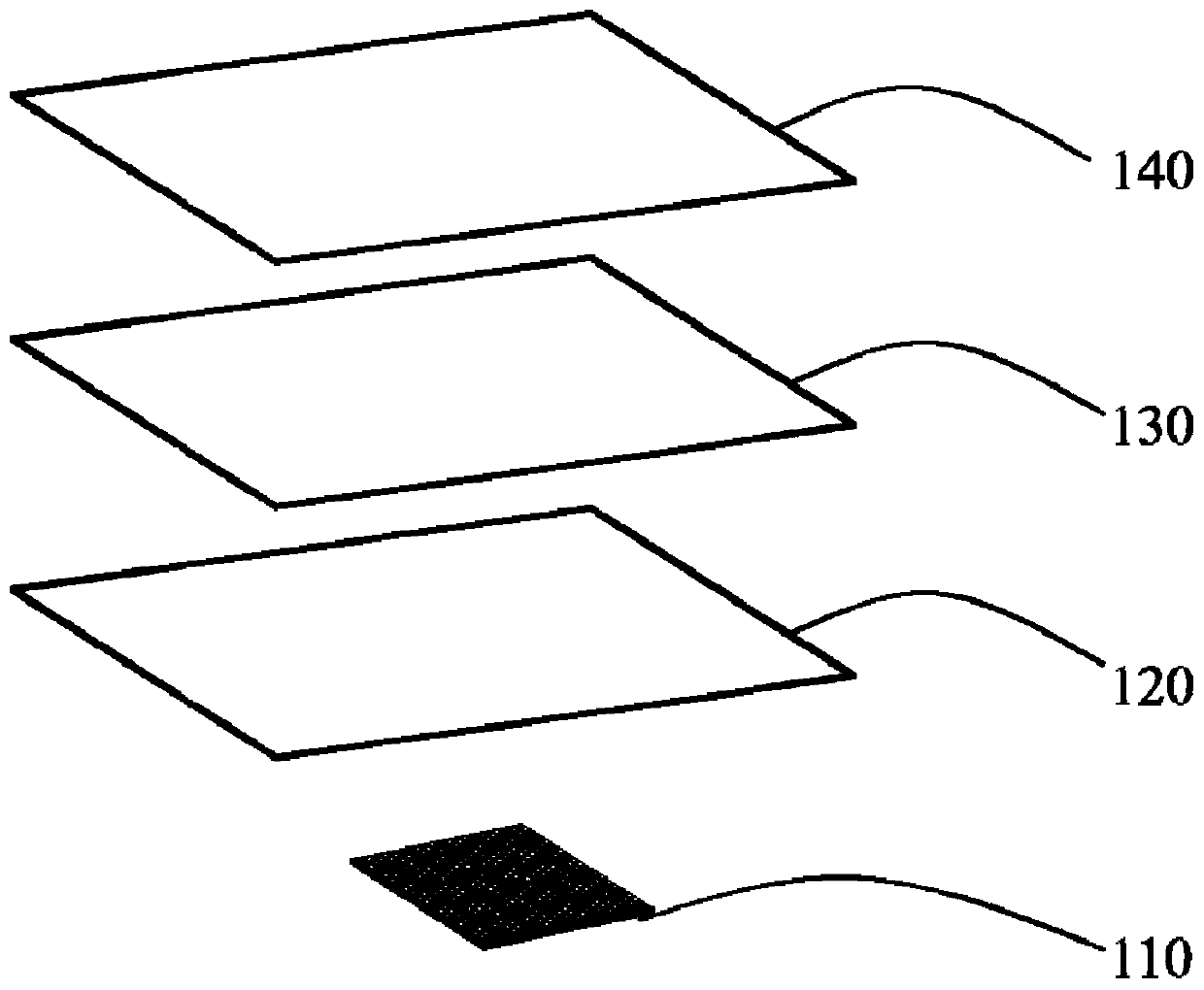
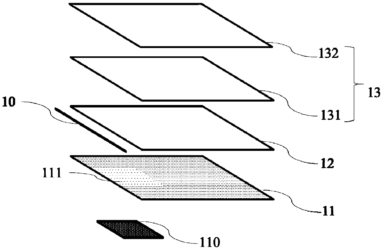
[0023] First, through figure 2 , image 3 , the backlight device according to Embodiment 1 of the present invention will be described. The backlight device according to Embodiment 1 of the present invention includes a light source 10 and a light guide plate 12 arranged on one side of the light source 10; a reflective sheet 11 arranged below the light guide plate 12; The optical film 13, and the fingerprint recognition device 110 arranged under the reflection sheet 11. The reflective sheet 11 is provided with an infrared transparent reflective film 111 , and the infrared transparent reflective film 111 reflects visible light, so that the infrared light is collected by the fingerprint identification device 110 after passing through the infrared transparent reflective film 111 . The optical film includes a diffusion sheet 131 and a prism sheet 132 .

[0024] In the backlight device of this embodiment, the infrared signal carrying biological fingerprint information effectively...

Embodiment 2

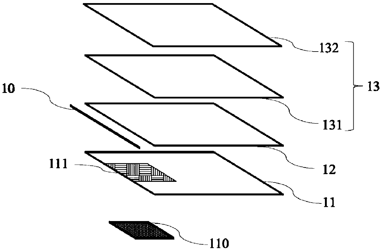
[0029] Please refer to image 3 , is an exploded view of the backlight module of the fingerprint identification terminal device according to Embodiment 2 of the present invention. In the following, only the differences between Embodiment 2 and Embodiment 1 will be described, and the similarities will not be repeated here.

[0030] The infrared transparent reflective film 111 is spliced ​​and formed on the reflective sheet 11 . The infrared transparent reflective film 111 is a composite thin film with a multi-layer structure, including negative refractive index materials.


PUM


Abstract

The invention discloses a backlight device for fingerprint identification under a screen and electronic equipment. The backlight device comprises a light source, a light guide plate arranged on one side of the light source, a reflector plate arranged below the light guide plate, an optical film arranged above the light guide plate, and a fingerprint recognition device arranged below the reflectorplate. An infrared transparent reflecting film is arranged on the reflector plate, the position of the infrared transparent reflecting film corresponds to the position of the fingerprint recognition device, and the infrared transparent reflecting film reflects visible light and transmits infrared light, so that the infrared light is collected by the fingerprint recognition device after transmitting the infrared transparent reflecting film.

Description

technical field [0001] The invention relates to the technical field of communication, in particular to a backlight device and electronic equipment used for fingerprint recognition in an LCD screen. Background technique [0002] Fingerprint sensing and matching is a reliable and widely used technology. A common method of fingerprint identification involves scanning a sample fingerprint or an image thereof and storing the image and / or unique characteristics of the fingerprint image, the characteristics of the sample fingerprint can be compared with information from reference fingerprints already present in a database to determine the correct identification of the user , for example for verification purposes. In particular, in-display fingerprint recognition is currently becoming more and more popular due to its ease of operation and versatility, and its suitability for compact portable electronic devices. [0003] The fingerprint recognition display device in the LCD screen ...

Claims


Application Information

Patent Timeline
Patent Type & Authority Applications(China)
IPC IPC(8): G02F1/13357G02F1/1333G06K9/00
CPCG02F1/1336G02F1/133605G02F1/13338G02F1/133606G02F1/133607G06V40/13
Inventor 张小齐曾晓虎彭益庄世强
Owner SHENZHEN LONGLI TECH CO LTD
Why Eureka
Try Eureka