Steel rail surface defect three-dimensional detection system and method
A technology of three-dimensional detection and rail, which is applied in the direction of optical detection of defects/defects, etc., can solve the problems of limited detection accuracy, cumbersome calibration process, and large amount of calculation, and achieve low misjudgment rate, high reliability, and improved accuracy.
- Summary
- Abstract
- Description
- Claims
- Application Information
AI Technical Summary
Problems solved by technology
Method used
Image
Examples
Embodiment 1
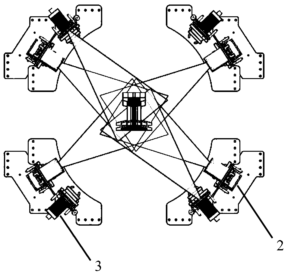
[0073] This embodiment 1 provides a three-dimensional detection system for rail surface defects, a three-dimensional detection system for rail surface defects, including four sets of detection mechanisms assembled into one and facing the same direction, and an analysis unit 1 electrically connected to the four sets of detection mechanisms Each group of detection mechanisms includes a laser unit 2 and a camera unit 3 assembled together and facing the same direction, and the four groups of detection mechanisms are respectively arranged on the upper left, upper right, lower left and lower right of the rail (such as figure 1 shown);
[0074] The laser unit 2 projects the laser line onto the surface of the rail beam, and the laser lines emitted by the four laser units 2 are located on the same plane, and form a closed curve on the tread surface, bottom surface and two ventral surfaces of the rail beam;
[0075] The camera unit 3 collects the projection of the laser line on the rail...
Embodiment 2
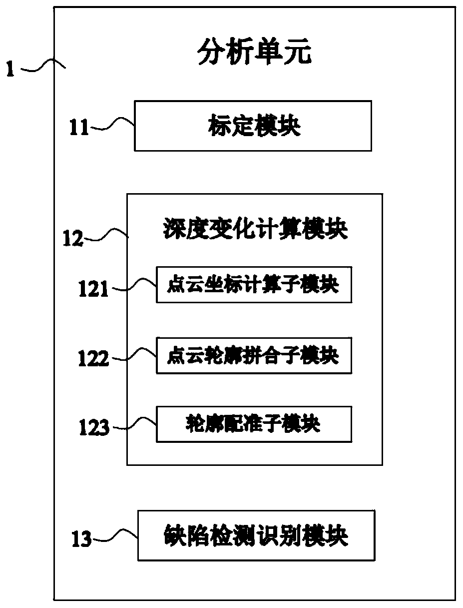
[0079] Such as figure 2 As shown, this embodiment 2 provides a three-dimensional detection system for rail surface defects on the basis of embodiment 1, and this embodiment 2 further defines that the analysis unit 1 includes the following parts:
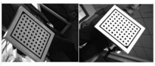
[0080] The calibration module 11 is used to calibrate multiple parameters of the detection system, the parameters include camera internal parameters, camera external parameters, laser plane parameters and the direction of motion of the rail;
[0081] The depth change calculation module 12 is used to solve the three-dimensional coordinates of the rail surface according to the calibrated parameters and the image irradiated on the rail surface by the laser line, and then calculate the depth change distribution map of the rail surface;
[0082] The defect detection and identification module 13 is used to identify defects from the distribution map of rail surface depth variation, and judge the types of defects (including rolling scars, g...
Embodiment 3
[0105] Such as Figure 10 As shown, this embodiment 3 provides a three-dimensional detection method for rail surface defects using the system described in the above embodiments, which specifically includes the following steps:
[0106] S1: The laser lines on the same plane are projected onto the rail beam surface from four directions at the same time through the laser unit 2. Enclosed on the ventral surface to form a closed curve;
[0107] S2: collect the projection of the laser line on the rail beam through the camera unit 3, and provide the collected laser line image to the analysis unit 1;
[0108] S3: Process and calculate the laser line image through the analysis unit 1, analyze the deformation of the laser line on the surface of the rail beam, and obtain the defect information on the rail surface.
[0109] Such as Figure 11 As shown, the specific method of step S3 is as follows:
[0110] S3.1: Taking the moving direction of the rail as the z-axis, calibrate multiple...
PUM
 Abstract
Description
Claims
Application Information
 - Generate Ideas
- Intellectual Property
- Life Sciences
- Materials
- Tech Scout
- Unparalleled Data Quality
- Higher Quality Content
- 60% Fewer Hallucinations
Browse by: Latest US Patents, China's latest patents, Technical Efficacy Thesaurus, Application Domain, Technology Topic, Popular Technical Reports.
© 2025 PatSnap. All rights reserved.Legal|Privacy policy|Modern Slavery Act Transparency Statement|Sitemap|About US| Contact US: help@patsnap.com


