
Test fixture for quasi-in-situ detection of membrane electrode perforation point by utilizing infrared thermal imaging

A technology of infrared thermal imaging and test fixtures, which is applied in the application of electrical devices to test fluid tightness, measuring devices, optical radiation measurement, etc., can solve the mechanical damage of membrane electrodes and the inability to effectively identify the formation time of each point. Membrane electrode performance or durability and other issues to achieve the effect of improving life expectancy

Active Publication Date: 2020-05-08
WUHAN UNIV OF TECH
View PDF15 Cites 3 Cited by
  • Summary
  • Abstract
  • Description
  • Claims
  • Application Information

AI Technical Summary

Problems solved by technology

However, for applying this method to an actual single cell, the membrane electrode with suspected perforation is often taken out of the test fixture and then reinstalled in a specially designed infrared test fixture. The disadvantages of this method are: on the one hand , the membrane electrode needs to be replaced into a custom-made infrared fixture for testing after removal, which may cause permanent mechanical damage to the membrane electrode
On the other hand, there may be many perforation positions in the final state, and it is impossible to effectively identify the formation time of each point and the impact on the performance or durability of the membrane electrode.

Method used


Image

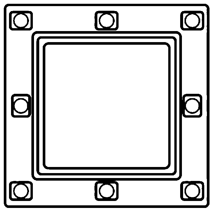
  • Test fixture for quasi-in-situ detection of membrane electrode perforation point by utilizing infrared thermal imaging
  • Test fixture for quasi-in-situ detection of membrane electrode perforation point by utilizing infrared thermal imaging
  • Test fixture for quasi-in-situ detection of membrane electrode perforation point by utilizing infrared thermal imaging

Examples


Embodiment Construction

[0027] The technical solutions in the embodiments of the present invention will be clearly and completely described below in conjunction with the accompanying drawings in the embodiments of the present invention. Obviously, the described embodiments are only a part of the embodiments of the present invention, rather than all the embodiments. Based on the embodiments of the present invention, all other embodiments obtained by those of ordinary skill in the art without creative work shall fall within the protection scope of the present invention.

[0028] It should be noted that the experimental methods described in the following embodiments are conventional methods unless otherwise specified, and the reagents and materials, unless otherwise specified, can be obtained from commercial sources; in the description of the present invention, The terms "horizontal", "vertical", "upper", "lower", "front", "rear", "left", "right", "vertical", "horizontal", "top", "bottom", The orientation ...


PUM


Abstract

The invention discloses a test fixture for quasi-in-situ detection of a membrane electrode perforation point by utilizing infrared thermal imaging. The test fixture comprises an anode end plate, an anode metal collector plate, an anode flow field plate, a fixing frame, an integrated cathode flow field plate and connecting rods, wherein the anode end plate, the anode metal collector plate, the anode flow field plate, the fixing frame and the cathode flow field plate are respectively arranged on two sides of the membrane electrode; the connecting rods penetrate through the two sides of the fixing frame and are arranged in parallel along the periphery of the fixing frame, the middle sections of the connecting rods are fixedly connected with the fixing frame, and the two ends of each connecting rod sequentially penetrate through the anode end plate, the anode metal collector plate, the anode flow field plate and the cathode flow field plate and are fixed through fastening devices. The testfixture provided by the invention has the functions of battery performance testing and infrared hole testing at the same time, can realize quasi-in-situ detection of the perforation position of a membrane electrode, avoids damage of the membrane electrode in a repeated disassembly process, can realize monitoring of a membrane perforation state evolution process, and is more beneficial to relatedresearch of a membrane perforation mechanism.

Description

Technical field [0001] The present invention relates to the technical field of fuel cells, and in particular to a test fixture for quasi-in-situ detection of perforation points of membrane electrodes using infrared thermal imaging. Background technique [0002] Durability is currently one of the important obstacles restricting the large-scale commercialization of proton exchange membrane fuel cells, which mainly depends on the membrane electrode, the core component. Generally speaking, the membrane electrode has seven layers, which are anode sealing frame, anode gas diffusion layer, anode catalyst layer, proton exchange membrane, cathode catalyst layer, cathode gas diffusion layer, and cathode sealing frame in order. During the long-term durability experiment, the proton exchange membrane will undergo chemical degradation and physical degradation processes, which will lead to the formation of pinholes, cracks, and thinning, resulting in an increase in hydrogen permeation current....

Claims


Application Information

Patent Timeline
Patent Type & Authority Applications(China)
IPC IPC(8): G01J5/00G01J5/02G01M3/40
CPCG01J5/00G01J5/0205G01J2005/0077G01M3/40
Inventor 潘牧何练傅鹏
Owner WUHAN UNIV OF TECH
Learn More