
Handle type blade with three pressure sensing holes at front edge of each element stage

A primitive-level, leading-edge technology, applied in pump components, non-variable-capacity pumps, components of pumping devices for elastic fluids, etc. The effect of light weight, improved measurement resolution, and reduced blade weight

Pending Publication Date: 2020-05-08
BEIHANG UNIV
View PDF0 Cites 3 Cited by
  • Summary
  • Abstract
  • Description
  • Claims
  • Application Information

AI Technical Summary

Problems solved by technology

[0012] The technical problem to be solved by the present invention is: the design of the existing compressor blades does not include the inter-stage aerodynamic parameter measurement design, resulting in the difficulty of accurately measuring the inter-stage flow field parameters in the narrow flow channel between the small-sized blade rows of the compressor, Invented a handle-type blade with three pressure-sensing holes on the leading edge of the elementary stage, which solved the technical problem that the accurate measurement of the flow field parameters between the stages could not be carried out in the narrow flow passage between the small-sized blade rows of the compressor

Method used


Image

  • Handle type blade with three pressure sensing holes at front edge of each element stage
  • Handle type blade with three pressure sensing holes at front edge of each element stage
  • Handle type blade with three pressure sensing holes at front edge of each element stage

Examples


Embodiment 1

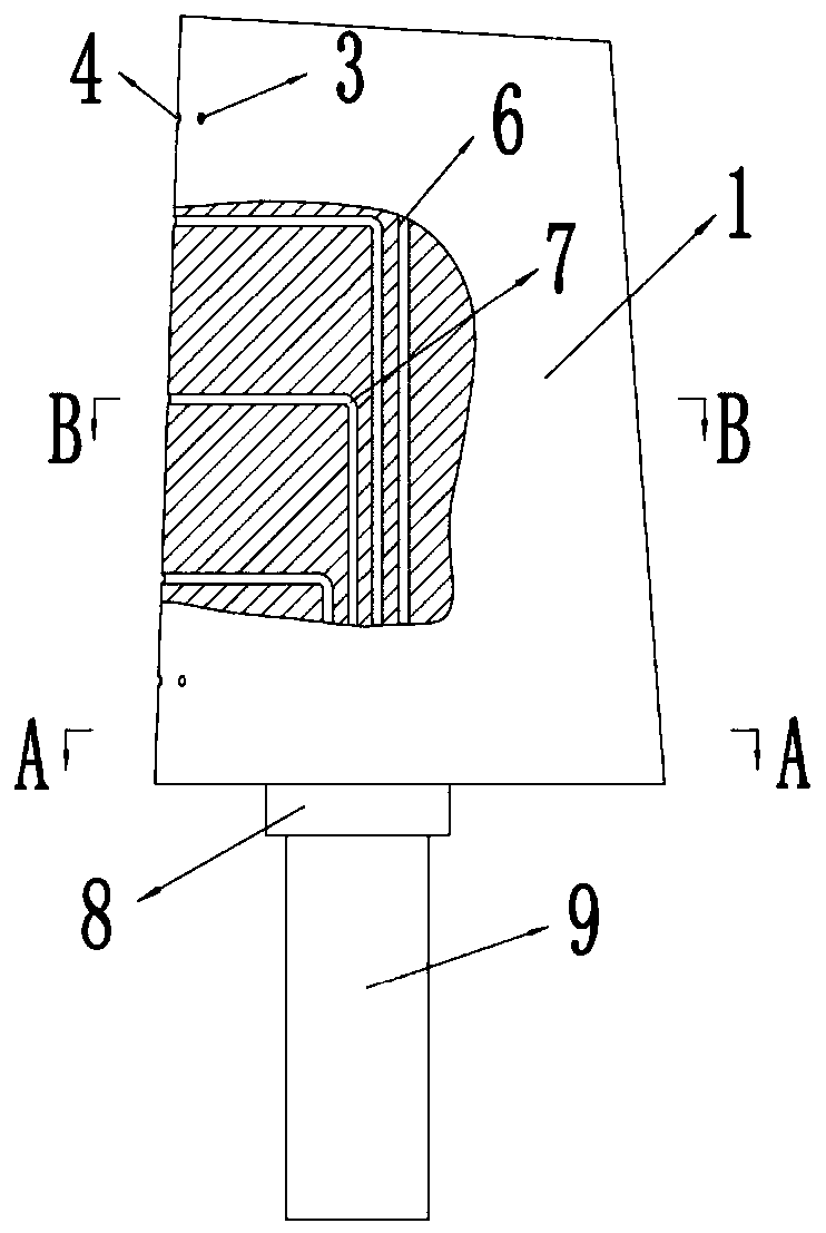
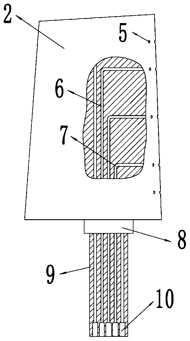
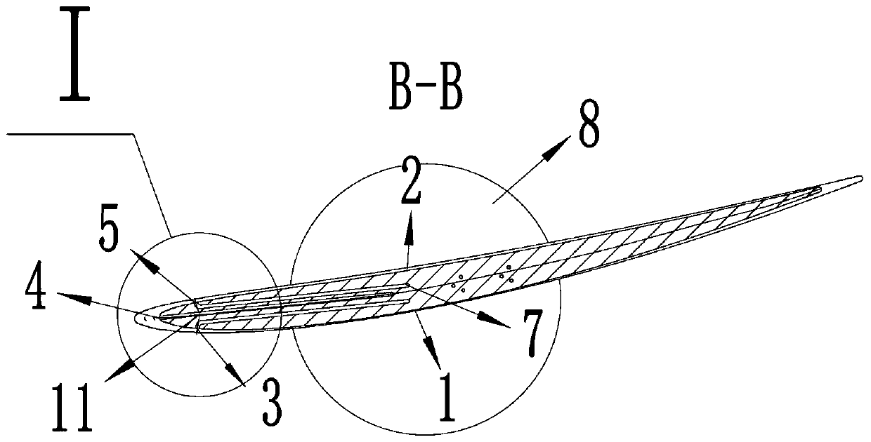
[0034] Such as figure 1 and figure 2 As shown, this embodiment introduces a handle-type blade with three pressure-sensing holes on the leading edge of the primitive level; the blade has a small twist and includes a blade suction surface (1), a blade pressure surface (2), Suction surface pressure sensing hole (3), leading edge point pressure sensing hole (4), pressure surface pressure sensing hole (5), pressure introduction channel (6), low loss elbow (7), handle boss (8), Handle (9), pressure induction tube interface (10). Among them, the blade has multiple rows of pressure sensing holes distributed along the leaf height direction, the center line of each row of pressure sensing holes is on the same primitive level, and the diameter of each hole is 0.4mm. From the direction of the leaf root, the first row of pressure sensing holes is 1mm away from the leaf root, the second row is at 25% of the leaf height, the third row is at 50% of the leaf height, the fourth row is at 75%...

Embodiment 2

[0039] Such as Figure 7 and Figure 8 As shown, this embodiment introduces a handle-type blade with three pressure-sensing holes on the leading edge of the primitive level; the blade has a certain twist, including the blade suction surface (1), the blade pressure surface (2), Suction surface pressure sensing hole (3), leading edge point pressure sensing hole (4), pressure surface pressure sensing hole (5), pressure introduction channel (6), low loss elbow (7), handle boss (8), Handle (9), pressure induction tube interface (10). Among them, the blade has multiple rows of pressure sensing holes distributed along the leaf height direction, the center line of each row of pressure sensing holes is on the same primitive level, and the diameter of each hole is 0.4mm. From the direction of the leaf root, the first row of pressure sensing holes is 1mm away from the leaf root, the second row is at 25% of the leaf height, the third row is at 50% of the leaf height, the fourth row is a...

Embodiment 3

[0045] Such as figure 1 and figure 2 As shown, this embodiment introduces a handle-type blade with three pressure-sensing holes on the leading edge of the primitive level; the blade has a small twist and includes a blade suction surface (1), a blade pressure surface (2), Suction surface pressure sensing hole (3), leading edge point pressure sensing hole (4), pressure surface pressure sensing hole (5), pressure introduction channel (6), low loss elbow (7), handle boss (8), Handle (9), pressure induction tube interface (10). Among them, the blade has multiple rows of pressure sensing holes distributed along the leaf height direction, the center line of each row of pressure sensing holes is on the same primitive level, and the diameter of each hole is 0.4mm. From the direction of the leaf root, the first row of pressure sensing holes is 1mm away from the leaf root, the second row is at 25% of the leaf height, the third row is at 50% of the leaf height, the fourth row is at 75%...


PUM

PropertyMeasurementUnit
Lengthaaaaaaaaaa
Diameteraaaaaaaaaa

Abstract

The invention discloses a handle type blade with three pressure sensing holes at the front edge of each element stage. The handle type blade comprises the pressure sensing holes, a pressure guiding channel, a handle, a pressure guiding pipe connector and a low-loss bent pipe. The front edge of the blade is provided with the multiple rows of pressure sensing holes in the blade height direction, each row comprises three pressure sensing holes which are respectively distributed at a front edge point of each element stage, a pressure surface and a suction surface; and the pressure guiding channelis respectively connected with orifices of the pressure sensing holes and the pressure guiding pipe connector, and the low-loss bent pipe is adopted at the bent part. According to the handle type blade, the total pressure, static pressure, deflection angle and Mach number of airflow at an outlet of a compressor rotor in the blade height direction and at the multiple element stage positions can besimultaneously measured, and the handle type blade is suitable for measuring the distribution of two-dimensional flow field parameters at the outlet of the rotor in the blade height direction. The handle type blade has the pneumatic performance and strength of a conventional blade, and importantly has the function of measuring the pneumatic parameters, and compared with a measurement technology ofa conventional probe and a blade type probe, the handle type blade has the advantages of no overhanging probe, no interference with a measured flow field structure, no influence on the pneumatic performance of the blade and high measurement parameter precision.

Description

technical field [0001] The invention belongs to the field of power machinery and relates to a compressor, in particular to a handle-type blade with three pressure-sensing holes on the leading edge of a primitive level. Background technique [0002] There are many ways to install the stator blades of the compressor to the hub, one of which is the handle fixed method. The blade root of the stator blade has a handle boss and a handle, and the blade can be fixed on the hub through structures such as collars and snap rings on the hub. This installation method is simple in structure, easy to disassemble and assemble, and is convenient to disassemble and replace a single blade. [0003] In the compressor, a cylinder coaxial with the compressor is used to cut the blade of the compressor, and the cross section of the compressor blade is called the primitive level of the blade. [0004] At present, in the process of aerodynamic design of compressor blades, it is first necessary to d...

Claims


Application Information

Patent Timeline
IPC IPC(8): F04D29/40F04D27/00
CPCF04D27/001F04D29/403
Inventor 马宏伟徐博闻夏晨希
Owner BEIHANG UNIV
Learn More