Cooling fan, air cooling system and engine

A cooling fan and air-cooling system technology, which is applied in the direction of engine components, engine cooling, machine/engine, etc., can solve the problems of reduced transmission efficiency, large wind resistance of blades on the windward side, and low efficiency of cooling blades, so as to optimize air volume, The effect of reducing wind resistance and improving transmission efficiency

Inactive Publication Date: 2020-05-08
CHONGQING LONCIN MOTOR +1
View PDF6 Cites 5 Cited by
  • Summary
  • Abstract
  • Description
  • Claims
  • Application Information

AI Technical Summary

Problems solved by technology

[0002] The engine usually needs to be connected to the gearbox to realize the speed change. The fan of the engine or the gearbox is usually used for air cooling. The tail of the blade of the current cooling fan is bent towards the side where the fan rotates. This structure results in a large wind resistance on the windward side of the blade. The efficiency of the blades is low, resulting in a reduction in the overall transmission efficiency of the transmission; at the same time, the noise is loud during use;

Method used


Image

  • Cooling fan, air cooling system and engine
  • Cooling fan, air cooling system and engine
  • Cooling fan, air cooling system and engine

Examples


Embodiment Construction

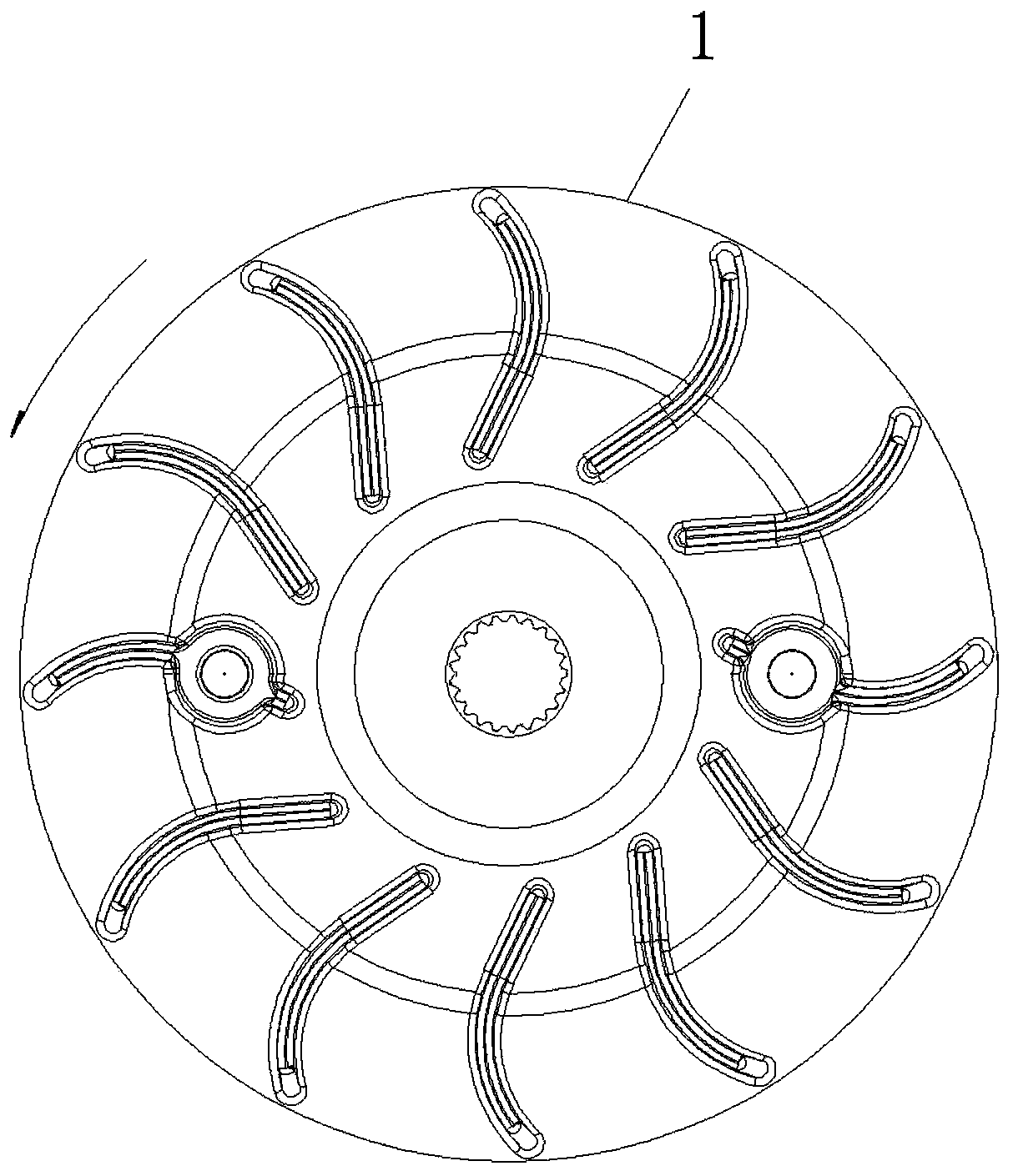
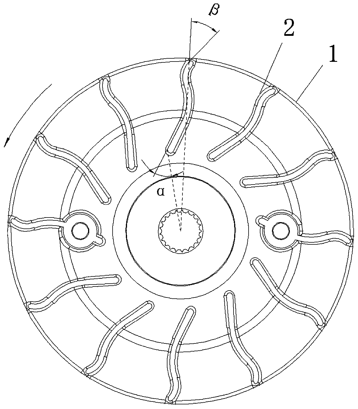
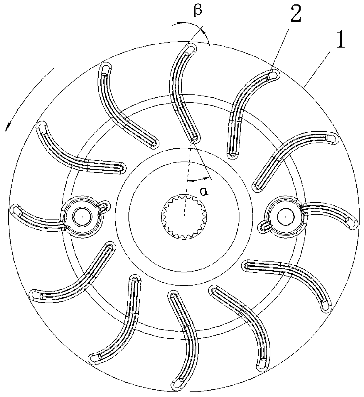
[0025] figure 1 It is a schematic diagram of the existing cooling fan structure; figure 2 Schematic diagram of the structure of the cooling fan of the present invention figure 1 ; image 3 Schematic diagram of the structure of the cooling fan of the present invention figure 2 ; Figure 4 for image 3 Schematic diagram of the side view structure; Figure 5 A schematic diagram of the structure of the engine case cover; Figure 6 A schematic diagram of the engine structure;

[0026] combine figure 1 As shown, the tail of the blade of the existing engine or reducer cooling fan is bent to the direction of rotation. When the head of the air flow blade flows to the tail, the wind flow has a radial outward flow trend based on centrifugal force, but the curved tail structure has a negative impact on the wind flow. The resistance makes the air flow have radial inward resistance. This structure makes the wind resistance caused by the blades to the air flow larger, resulting in ...


PUM


Abstract

The invention discloses a cooling fan, an air cooling system and an engine. The cooling fans are installed in the air cooling system and the engine respectively. Each cooling fan comprises a fan discand a plurality of blades connected to the fan disc and peripherally distributed. The tails of the blades are bent in the direction opposite to the rotating direction of the fan, wherein the cooling fan is in transmission fit with a driving wheel of a gearbox, the gearbox is of a CVT speed changing structure, the gearbox is integrated into an engine box, a guiding device is arranged at the inner side of an engine case cover and located between a driving shaft and a driven shaft, the upper end of the guiding device is provided with a flow guiding face, and the flow guiding face is inclined upwards from the inner side of the cooling fan to the side of an air outlet. The tails of the blades of the cooling fan are bent so that the windward sides of the blades can be in arc transition. An air flue damping coefficient is optimized, air flow is guided, and the wind resistance is effectively lowered; due to the structure, the wind resistance of the blades can be lowered, and the overall transfer efficiency of the gearbox can be improved. Meanwhile, the vortex phenomenon formed by the tails of the blades is avoided, the air volume in an air flue is optimized, the air cooling effect is improved, and noise is lowered.

Description

technical field [0001] The invention belongs to the technical field of motor vehicles and relates to a cooling fan, an air cooling system and an engine. Background technique [0002] The engine usually needs to be connected to the gearbox to realize the speed change. The fan of the engine or the gearbox is usually used for air cooling. The tail of the blade of the current cooling fan is bent toward the side where the fan rotates. The efficiency of the blades is low, resulting in a reduction in the overall transmission efficiency of the transmission; at the same time, the noise is loud during use; [0003] Therefore, it is necessary to change the structure of the blade angle of the cooling fan to reduce the wind resistance on the windward side of the blade, improve the transmission efficiency of the transmission, and reduce noise. Contents of the invention [0004] In view of this, the present invention provides a cooling fan, an air cooling system and an engine. By changi...

Claims


Application Information

Patent Timeline
Patent Type & Authority Applications(China)
IPC IPC(8): F01P5/02F01P5/04F04D25/08F04D29/38
CPCF01P5/02F01P5/04F04D25/08F04D29/38F04D29/384F04D29/388
Inventor 聂川陈艺方周良兵蒋博文凌磊
Owner CHONGQING LONCIN MOTOR
Why Eureka
Try Eureka