
Secondary lining trolley backform mounting device and constructing method thereof

A technology of installation device and jacking device, which is applied to shaft lining, tunnel lining, shaft equipment, etc., can solve the problems of increased engineering volume and construction difficulty, collision of top molds, inconvenient movement, etc., and achieves safe and reliable assembly process. The effect of avoiding mutual collision and reducing the difficulty of construction

Active Publication Date: 2020-05-08
长沙仪秀兴智能科技有限公司
View PDF5 Cites 0 Cited by
  • Summary
  • Abstract
  • Description
  • Claims
  • Application Information

AI Technical Summary

Problems solved by technology

[0004] 1. It is necessary to increase the height of the vault at the lifting point and expand the excavation, which increases the amount of work and construction difficulty;
[0005] 2. Use the pre-embedded anchor rod as the lifting point, and use the wire rope to lift the four corners, which has poor maneuverability and potential safety hazards;
[0006] 3. Due to the limitation of the bearing capacity of the pre-embedded anchor, it is necessary to install the bracket and the top form separately. Install the bracket first and then install the top form. When installing the top form, hang the four corners, and the top form is open. The stress state is not good, and it is easy to deform the top mold;
[0007] 4. After each section of the top mold is hoisted in place, the trolley needs to be driven under the top mold. After connecting with the bracket, the trolley will drive away again, and then assemble the next section. Due to the heavy weight and large inertia of the trolley, it is difficult to move Inconvenient and low positioning accuracy, it is easy to cause the two top molds to collide with each other

Method used


Image

  • Secondary lining trolley backform mounting device and constructing method thereof
  • Secondary lining trolley backform mounting device and constructing method thereof
  • Secondary lining trolley backform mounting device and constructing method thereof

Examples


Embodiment Construction

[0037] The following will combine Figure 1-Figure 8 The present invention is described in detail, and the exemplary embodiments and descriptions of the present invention are used to explain the present invention, but not to limit the present invention.

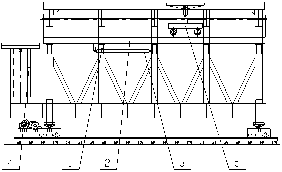
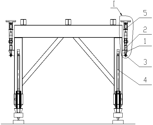
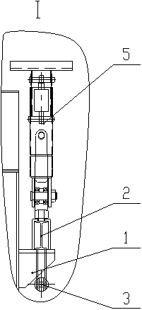
[0038] A roof mold installation device for a two-liner platform, including a sliding groove group 1, a guide rail device 2, a guide rail moving mechanism 3, a jacking device 4, and a transfer device 5. The space where the guide rail device 2 slides longitudinally, the guide rail device 2 can move longitudinally along the sliding groove group 1 under the action of the guide rail moving mechanism 3, and the jacking device 4 is installed on the bottom longitudinal beam of the mast to lift the top mold to the rotary The transfer device 5 can move along the guide rail device 2 and can be raised and lowered, and is used to transfer the top form and move the top form to the installation position and place it on the table beam.

[0...


PUM


Abstract

The invention relates to a secondary lining trolley backform mounting device. The secondary lining trolley backform mounting device comprises chute groups, a guide rail device, a guide rail moving mechanism, a jacking device and a transferring device; the chute groups are mounted on upright posts of a trolley gantry and is provided with space for the guide rail device to slide longitudinally; theguide rail device can move along the chute groups under the action of the guide rail moving mechanism; the jacking device is mounted on a longitudinal beam at the bottom of the gantry and is used forjacking a backform to a transfer height; and the transferring device can move along the guide rail device and can ascend and descend, and is used for transferring and moving the backform to a mountingposition, and placing the backform on a platform beam. The invention also provides a construction method applied to the device. The secondary lining trolley top die mounting device can realize the mounting of the backform of a secondary lining trolley, and is easy to operate and safe and reliable.

Description

technical field [0001] The invention relates to the field of tunnel construction equipment, in particular to a two-liner roof form installation device and a construction method applied to the device. Background technique [0002] At present, the second lining trolley of the tunnel is generally installed in the tunnel hole. Due to the limitation of the space in the hole, it is usually assembled by a loader supplemented by a manual hoist. The assembly process is: assembly preparation→determination of the lifting point position→the location of the vault lifting point Elevation and excavation → installation of anchor bolts → site leveling in the cave → laying trolley track → installation of running mechanism → installation of bottom longitudinal beam → installation of door frame → installation of scissors brace → installation of platform beam → installation of bracket → installation of roof Mold→Install side mold→Install side mold→Install hydraulic system→Complete machine debugg...

Claims


Application Information

Patent Timeline
IPC IPC(8): E21D11/10E21D11/40
CPCE21D11/102E21D11/40
Inventor 周桢
Owner 长沙仪秀兴智能科技有限公司
Learn More