
Uniformly-locked sealed protection door with transition threshold

A technology for airtight doors and sills, which is applied in windowsill/threshold, door leaf, window/door, etc. It can solve problems such as door leaves cannot be opened, seal wear is unbalanced, and precise alignment cannot be achieved, so as to improve the sealing protection effect and reduce force Stable and reasonable, the effect of enhancing the protective effect

Inactive Publication Date: 2020-05-08
CHINA INST OF BUILDING STANDARD DESIGN & RES +1
View PDF7 Cites 4 Cited by
  • Summary
  • Abstract
  • Description
  • Claims
  • Application Information

AI Technical Summary

Problems solved by technology

[0002] Airtight doors are used in the field of civil air defense engineering in order to protect and seal during wartime. However, when an explosion occurs, the door leaf of the existing airtight door will rebound, and the door leaf and the door frame will tend to separate, which may cause the door leaf to accept Unable to open after impact, unable to play corresponding role
For safety and protection, multiple locking structures are often used, but they are generally arranged at intervals on the opening and closing sides of the door frame and door leaf, and generally not on the hinged side, resulting in uneven rebound force on the seal when the door leaf is closed. In turn, the wear of the seals on different sides is unbalanced, and the sealing effect is not good.
The door frame is generally tensioned on one side during installation. When the door frame is stressed, it only acts on one side of the wall, which may easily cause the door frame to damage the wall and cause it to fall off.
In addition, single-side-mounted door frames are often used. When used in positions that require two-way force, such as connecting ports and partition partitions, in order to meet protection requirements, two single-side-mounted door frames are often used in combination, which has complex overall structures and poor protection effects. defect
[0003] The door leaf generally adopts a thicker size to increase the protective effect of the airtight door, and also increases the weight of the door leaf. During installation, due to the size and weight of the door leaf and the error during civil construction, the embedded parts on the door frame Inconsistent with the design, when the door leaf and the door frame are aligned and installed, it is easy to appear that the installation components do not match the design, and the precise alignment cannot be achieved. The hinges need to be adjusted or reworked, which is extremely inconvenient
And because of the characteristics of the airtight airtight door, after the door leaf is installed, it must be sealed with the door frame by extruding the sealing strip, and then it is required that the inside and outside of the door leaf and the door frame have different degrees of fit during the door leaf opening and closing process, and the inside and outside of the door leaf after closing The outer side and the door frame have the same degree of fit to ensure the airtight effect, but the existing hinge structure cannot achieve the above effect, so that there will be a gap between the door frame and the door leaf, which will easily lead to wear of the seal and poor airtightness Appear
In addition, under the action of the shock wave, the door leaf using the existing hinge structure may be damaged due to the rebound effect and the door leaf cannot be opened
[0004] The threshold of the existing protective door adopts the traditional living threshold, which has the disadvantages of complex structure, slow movement and limited protective effect

Method used


Image

  • Uniformly-locked sealed protection door with transition threshold
  • Uniformly-locked sealed protection door with transition threshold
  • Uniformly-locked sealed protection door with transition threshold

Examples


Embodiment Construction

[0048] The following will clearly and completely describe the technical solutions in the embodiments of the present invention in conjunction with the accompanying drawings. Obviously, the described embodiments are only some of the embodiments of the present invention, not all of them. Based on the embodiments of the present invention, all other embodiments obtained by persons of ordinary skill in the art without making creative efforts belong to the protection scope of the present invention.

[0049] In the description of this patent, it is to be understood that the terms "center", "upper", "lower", "front", "rear", "left", "right", "vertical", "horizontal", The orientation or positional relationship indicated by "top", "bottom", "inner", "outer", etc. is based on the orientation or positional relationship shown in the drawings, and is only for the convenience of describing this patent and simplifying the description, rather than indicating or implying References to devices or...


PUM


Abstract

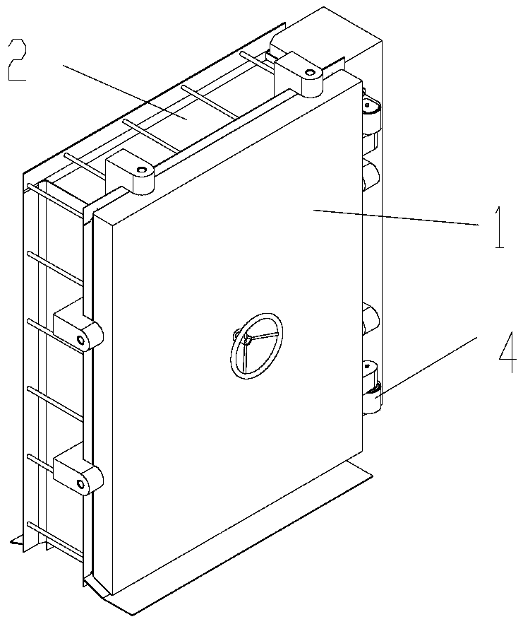
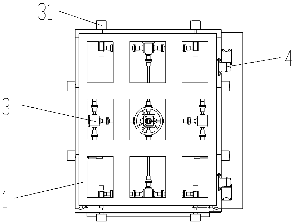
The invention discloses a uniformly-locked sealed protection door with a transition threshold comprising a door fan, a door frame and locking mechanisms. The door frame is set in walls; the door fan is connected with the walls through hinges and can be closed into the door frame through the locking mechanisms; the door frame is symmetrical, effectively enhancing the strength of the structure, andcan be adapted to install two door fans where needed; a transition door frame is set at the lower part of the door frame to make up for the defects of complex structure and poor protection effect of existing door frames; uniform locking structure is used to make the door fan under uniform force and, together with horizontally moving hinges, make the door fan and the door frame parallel, effectively enhancing the sealing and protection effects; the uniform locking structure and the horizontally moving hinges working together also effectively avoid the situation where the door fan rebounds underimpact and causes damages to the hinges so the door cannot open; and two sets of seals are arranged between the door fan and the door frame to enhance the sealing effect. The invention has the advantages of good sealing and protection effects, stable and reliable overall structure, convenient installation and good locking effect.

Description

technical field [0001] The invention relates to the technical field of civil air defense equipment, in particular to the technical field of civil air defense doors, and in particular to a transitional threshold protection airtight door with uniform distribution and locking. Background technique [0002] Airtight doors are used in the field of civil air defense engineering in order to protect and seal during wartime. However, when an explosion occurs, the door leaf of the existing airtight door will rebound, and the door leaf and the door frame will tend to separate, which may cause the door leaf to accept After the impact, it cannot be opened and cannot play the corresponding role. For safety and protection, multiple locking structures are often used, but they are generally arranged at intervals on the opening and closing sides of the door frame and door leaf, and generally not on the hinged side, resulting in uneven rebound force on the seal when the door leaf is closed. I...

Claims


Application Information

Patent Timeline
Patent Type & Authority Applications(China)
IPC IPC(8): E06B5/10E06B1/52E06B1/70E06B3/36E06B7/22E06B3/70E05D7/081E05C9/06
CPCE05C9/063E05D7/081E06B1/526E06B1/70E06B3/36E06B3/70E06B3/7017E06B5/10E06B7/2312
Inventor 卢屹东彭飞张瑞龙潘隆帮江漪张学礼徐泉王伟孙春燕王建昆周冉王磊韩洋洋
Owner CHINA INST OF BUILDING STANDARD DESIGN & RES
Learn More