
Combined connection structure for mining excavator chassis and mining excavator

A combined connection and excavator technology, applied in mechanically driven excavators/dredgers, earth movers/shovels, construction, etc., can solve the problem of weakening overall strength and stiffness, raising the overall height of the chassis, and uneven transition and other problems, to achieve the effect of strong functionality, reducing overall height and reducing stress

Active Publication Date: 2021-07-27
XUZHOU XCMG MINING MACHINERY CO LTD
View PDF8 Cites 0 Cited by
  • Summary
  • Abstract
  • Description
  • Claims
  • Application Information

AI Technical Summary

Problems solved by technology

[0003] The existing large-scale mining excavator chassis is divided into two types of assembly and connection methods: lap joint and lateral connection. The lap joint connection can easily increase the overall height of the chassis. In order to ensure the height limit of the chassis, The height of the middle frame is properly compressed, and the overall strength and rigidity will be weakened; while the lateral connection is directly provided with a lateral mounting plate on the longitudinal beam, and a threaded mounting hole, which is realized by using bolts. The lateral connection between the middle frame and the longitudinal beam, the bolts of this installation method are completely subjected to the combined action of shear force and tension force, and are easily damaged
[0004] Previously, the R&D personnel designed a chassis connection structure and applied for a patent. Its name is: combined construction machinery chassis connection structure (patent number: 2014204867656). Heavy, relatively poor strength when bearing bending moment and torque load, not as strong as stepped structure
At the same time, the disclosed chassis connection structure directly welds the thick plate with the longitudinal beam transverse thin plate and the longitudinal beam lateral thin plate. The transition of material “force flow” is not smooth, which is easy to cause stress concentration, and it is very easy to produce tiny cracks at the butt weld of the two plates , resulting in product defects

Method used


Image

  • Combined connection structure for mining excavator chassis and mining excavator
  • Combined connection structure for mining excavator chassis and mining excavator
  • Combined connection structure for mining excavator chassis and mining excavator

Examples


Embodiment Construction

[0031] In order to make the objectives, technical solutions and advantages of the present invention clearer, the technical solutions in the embodiments of the present invention will be described in more detail below in conjunction with the drawings in the embodiments of the present invention. In the drawings, the same or similar reference numerals denote the same or similar elements or elements having the same or similar functions throughout. The described embodiments are some, but not all, embodiments of the invention. The embodiments described below by referring to the figures are exemplary and are intended to explain the present invention and should not be construed as limiting the present invention. Based on the embodiments of the present invention, all other embodiments obtained by persons of ordinary skill in the art without making creative efforts belong to the protection scope of the present invention. Embodiments of the present invention will be described in detail b...


PUM


Abstract

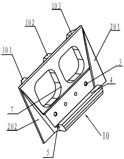
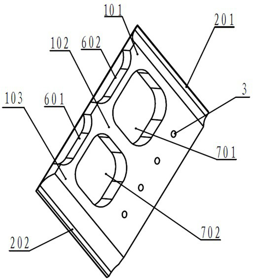
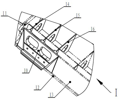
The invention discloses a combined connection structure for the chassis of a mining excavator and a mining excavator. The combined connection structure includes a double-bearing connecting device and a connecting device on the upper part of the longitudinal beam; the double-bearing connecting device is installed at the side plate of the longitudinal beam, and the longitudinal beam The upper connection device is installed at the top plate of the longitudinal beam, the upper part of the vehicle frame connection plate is connected with the upper connection device of the longitudinal beam, and the lower part of the vehicle frame connection plate is connected with the double load-bearing connection device. The invention can effectively protect the bolts, prevent yield failure, reduce the overall height of the chassis without restricting the design height of the vehicle frame, and improve the overall rigidity of the vehicle frame.

Description

technical field [0001] The invention relates to a combined connection structure for a mining excavator chassis, which belongs to the field of engineering machinery. Background technique [0002] Large-scale construction machinery, especially large-scale mining excavators, have a large chassis structure and heavy overall weight. They need to be disassembled during actual hoisting and transportation. Therefore, the chassis structure for large-scale mining excavators Generally, the chassis structure is divided into three parts: the frame structure domain in the middle, the longitudinal beam structure on both sides, which is convenient for disassembly and assembly. The longitudinal beam structure on both sides is connected with the frame structure in the middle by bolts and washers. [0003] The existing large-scale mining excavator chassis is divided into two types of assembly and connection methods: lap joint and lateral connection. The lap joint connection can easily increas...

Claims


Application Information

Patent Timeline
Patent Type & Authority Patents(China)
IPC IPC(8): E02F3/04E02F9/08
CPCE02F3/04E02F9/08
Inventor 焦青杨裕丰王勇丁跃进吴庆礼刘永参王冉冉渠立红张亚雄
Owner XUZHOU XCMG MINING MACHINERY CO LTD
Learn More