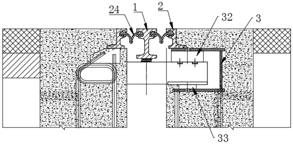
The Repairing Method of Bridge Modular Expansion Joint
A repair method and technology for expansion joints, applied in the field of expansion joint repairs, can solve problems such as poor economy, difficult maintenance, and increased maintenance costs, and achieve the effects of alleviating traffic pressure on bridge decks, reducing dust emissions, and improving repair efficiency
- Summary
- Abstract
- Description
- Claims
- Application Information
AI Technical Summary
Problems solved by technology
Method used
Image
Examples
Embodiment 1
[0051] 1. The center beam 1 is damaged, but the telescopic box 3 is not damaged
[0052] Wherein, the damage of the central sill 1 is generally broken or deformed.
[0053] Step 1: Locate the damaged position of the central sill 1 and determine the cutting area; specifically, use a ruler to measure the parallelism between the central sill 1 and the road surface, and the non-parallel part is the damaged position of the central sill 1.
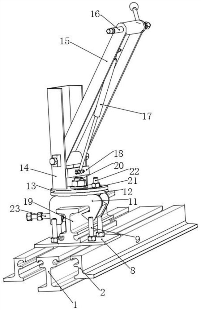
[0054] Step 2: Fix the fixture of the section steel tooling 5 equipped with the rail cutting machine on the center beam 1, cut off and remove the broken center beam 1 by the rail cutting machine.
[0055] Step three, such as Figure 5 As shown, a notch is formed at the excised center beam 1, and the bottom of the side beam 2 corresponding to the notch is respectively welded with a first mounting part 25 and a second mounting part 26, wherein the first mounting part 25 is installed in the first The center of the member 25 is arranged symmetrica...
Embodiment 2
[0061] 2. The center beam 1 is not damaged, but the telescopic box 3 is damaged
[0062] Wherein, the damage of telescopic box 3 is generally that the upper support 32 and the lower support 33 are severely damaged or fall off.
[0063] Step 1, locate the position of the damaged telescopic box 3, draw a line on the upper edge of the telescopic box 3 loam cake 31, use a concrete 7 cutter to cut the seam, and use a rock drill to chisel away the concrete 7 above the telescopic box 3 loam cake 31. As shown in Figure 6(a).
[0064] Step 2, as shown in Figure 6(b), the upper cover 31 corresponding to the damaged area of the telescopic box 3 is cut, as Figure 6(c) , 6(d) As shown, use the crowbar 4 to prop up the upper area of the telescopic box 3, take out the damaged upper support 32 or directly install a new upper support 32, use the tooling 5 to take out the damaged lower support 33 or directly install a new lower support 33 . Wherein, the frock 5 includes a cross arm 28 ...
Embodiment 3
[0071] 3. Some expansion joints are damaged
[0072] Step 1: Locate the location of the damaged expansion joint, mark the position where the expansion joint needs to be replaced, use a concrete 7 cutting machine to cut the joint, and use a rock drill to chisel out the concrete 7;
[0073] Step 2: Fix the steel fixture 5 fixture installed with the rail cutting machine on the middle beam 1, cut and remove the side beam 2 and the middle beam 1 corresponding to the damaged expansion joint through the rail cutting machine;
[0074] Step 3: Hoist the new expansion joint to the removal site, butt and weld it with the original expansion joint.
[0075] Specifically, when the new expansion joint is welded and installed with the original expansion joint, attention should be paid to:
[0076] (1) Arrange the pre-embedded steel bar 6 to make it smooth, and determine the detailed plan for the expansion joint installation according to the actual size of the pre-embedded steel bar 6.
[00...
PUM
 Abstract
Description
Claims
Application Information
 - Generate Ideas
- Intellectual Property
- Life Sciences
- Materials
- Tech Scout
- Unparalleled Data Quality
- Higher Quality Content
- 60% Fewer Hallucinations
Browse by: Latest US Patents, China's latest patents, Technical Efficacy Thesaurus, Application Domain, Technology Topic, Popular Technical Reports.
© 2025 PatSnap. All rights reserved.Legal|Privacy policy|Modern Slavery Act Transparency Statement|Sitemap|About US| Contact US: help@patsnap.com


