Bridge modular expansion joint repairing method
A repair method and technology for expansion joints, applied in the field of expansion joint repairs, can solve the problems of poor economy, difficult maintenance, time-consuming and manpower consumption, etc., so as to relieve the traffic pressure on the bridge deck, reduce dust emissions, and save construction time Effect
- Summary
- Abstract
- Description
- Claims
- Application Information
AI Technical Summary
Problems solved by technology
Method used
Image
Examples
Embodiment 1
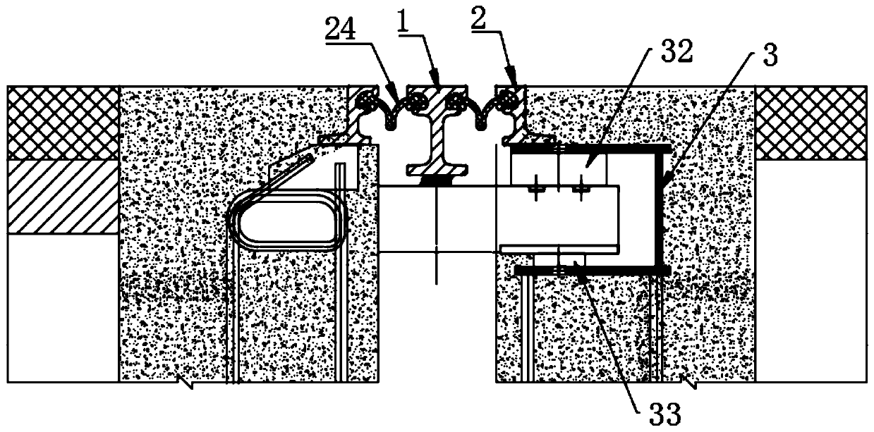
[0051] 1. The center beam 1 is damaged, but the telescopic box 3 is not damaged
[0052] Wherein, the damage of the central sill 1 is generally broken or deformed.
[0053] Step 1: Locate the damaged position of the central sill 1 and determine the cutting area; specifically, use a ruler to measure the parallelism between the central sill 1 and the road surface, and the non-parallel part is the damaged position of the central sill 1.
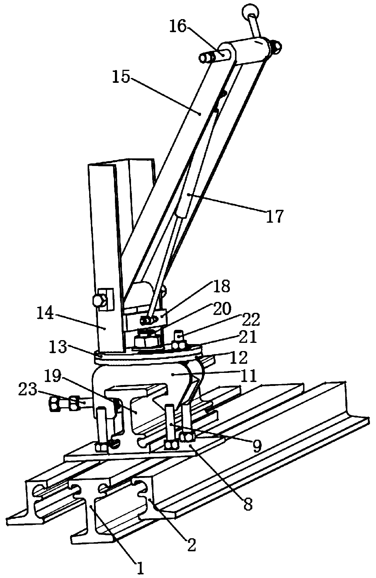
[0054] Step 2, fixing the profiled steel tooling 5 clamps equipped with the rail cutting machine on the center beam 1, cutting off and removing the broken center beam 1 by the rail cutting machine.
[0055] Step three, such as Figure 5 As shown, a notch is formed at the excised center beam 1, and the bottom of the side beam 2 corresponding to the notch is respectively welded with a first mounting part 25 and a second mounting part 26, wherein the first mounting part 25 is installed in the first The center of the piece 25 is arranged symmetric...
Embodiment 2
[0061] 2. The center beam 1 is not damaged, but the telescopic box 3 is damaged
[0062] Wherein, the damage of telescopic box 3 is generally that the upper support 32 and the lower support 33 are severely damaged or fall off.
[0063] Step 1, locate the position of the damaged telescopic box 3, draw a line on the upper edge of the telescopic box 3 loam cake 31, use a concrete 7 cutter to cut the seam, and use a rock drill to chisel away the concrete 7 above the telescopic box 3 loam cake 31. As shown in Figure 6(a).
[0064] Step 2, as shown in Figure 6(b), the upper cover 31 corresponding to the damaged area of the telescopic box 3 is cut, as Figure 6(c) , 6(d) As shown, use the crowbar 4 to prop up the upper area of the telescopic box 3, take out the damaged upper support 32 or directly install a new upper support 32, use the tooling 5 to take out the damaged lower support 33 or directly install a new lower support 33 . Wherein, the frock 5 includes a cross arm 28 ...
Embodiment 3
[0071] 3. Some expansion joints are damaged
[0072] Step 1, locate the position of the damaged expansion joint, mark the position where the expansion joint needs to be replaced, use the concrete 7 cutting machine to cut the seam, and use the rock drill to remove the concrete 7;
[0073] Step 2, fixing the profiled steel tooling 5 clamps equipped with a rail cutting machine on the middle beam 1, cutting and removing the side beams 2 and the middle beam 1 corresponding to the damaged expansion joints by the rail cutting machine;
[0074] Step 3: Hoist the new expansion joint to the removal site, butt and weld it with the original expansion joint.
[0075] Specifically, when the new expansion joint is welded and installed with the original expansion joint, attention should be paid to:
[0076] (1) Arrange the pre-embedded steel bar 6 to make it smooth, and determine the detailed plan for the installation of expansion joints according to the actual size of the pre-embedded steel...
PUM
 Abstract
Description
Claims
Application Information
 - R&D
- Intellectual Property
- Life Sciences
- Materials
- Tech Scout
- Unparalleled Data Quality
- Higher Quality Content
- 60% Fewer Hallucinations
Browse by: Latest US Patents, China's latest patents, Technical Efficacy Thesaurus, Application Domain, Technology Topic, Popular Technical Reports.
© 2025 PatSnap. All rights reserved.Legal|Privacy policy|Modern Slavery Act Transparency Statement|Sitemap|About US| Contact US: help@patsnap.com


