
Spraying device for PTC heating material for toilet ring and spraying method

A technology for heating materials and spraying devices, which is applied in the direction of spraying devices, liquid spraying devices, and devices for coating liquid on the surface, etc. It can solve the problems of uneven heating temperature of the toilet seat, low spraying efficiency, and easy to be sprayed out of bounds, etc., to achieve Avoid incomplete drying and improve spraying efficiency

Active Publication Date: 2020-05-08
SUZHOU LUZHIYAO TECH
View PDF13 Cites 0 Cited by
  • Summary
  • Abstract
  • Description
  • Claims
  • Application Information

AI Technical Summary

Problems solved by technology

[0002] The setting of the PTC heating element can heat the toilet seat at a constant temperature, but it will lead to uneven heating temperature of the toilet seat. In order to avoid uneven temperature, people began to try to coat the PTC polymer material on the lower side of the toilet seat as a heating layer.
[0003] Usually the PTC polymer material is used as the heating layer to spray the PTC polymer material on the lower part of the toilet seat. The spraying efficiency of the conventional spraying device is low, and it is difficult to meet the needs of high-efficiency production; at the same time, the PTC polymer material is easily damaged during the spraying process. Spraying is out of bounds, resulting in the position that should not be sprayed is also covered by the PTC polymer material. Not only is it time-consuming and laborious to remove the PTC polymer material that is sprayed out of the bounds, but once the removal is not complete, leakage will occur due to the conductivity of the PTC polymer material Problems that affect the safety of the toilet seat

Method used


Image

  • Spraying device for PTC heating material for toilet ring and spraying method
  • Spraying device for PTC heating material for toilet ring and spraying method
  • Spraying device for PTC heating material for toilet ring and spraying method

Examples


Embodiment Construction

[0028] The present invention will be further described in detail below in conjunction with the accompanying drawings, so that those skilled in the art can implement it with reference to the description.

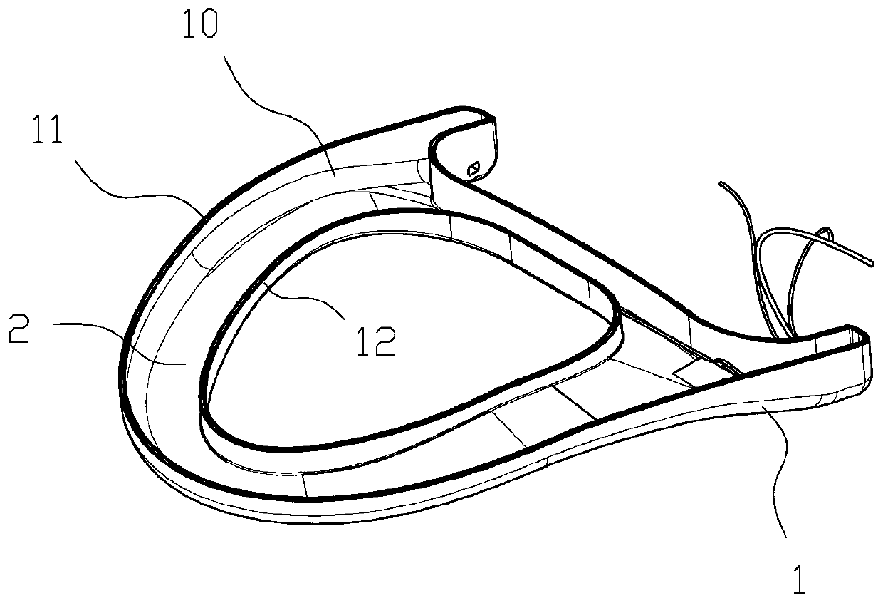
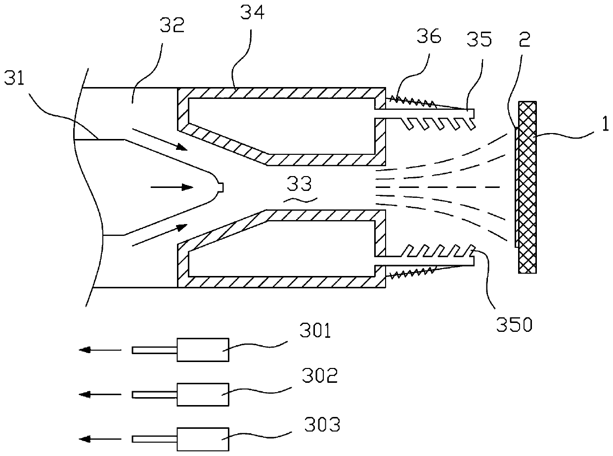
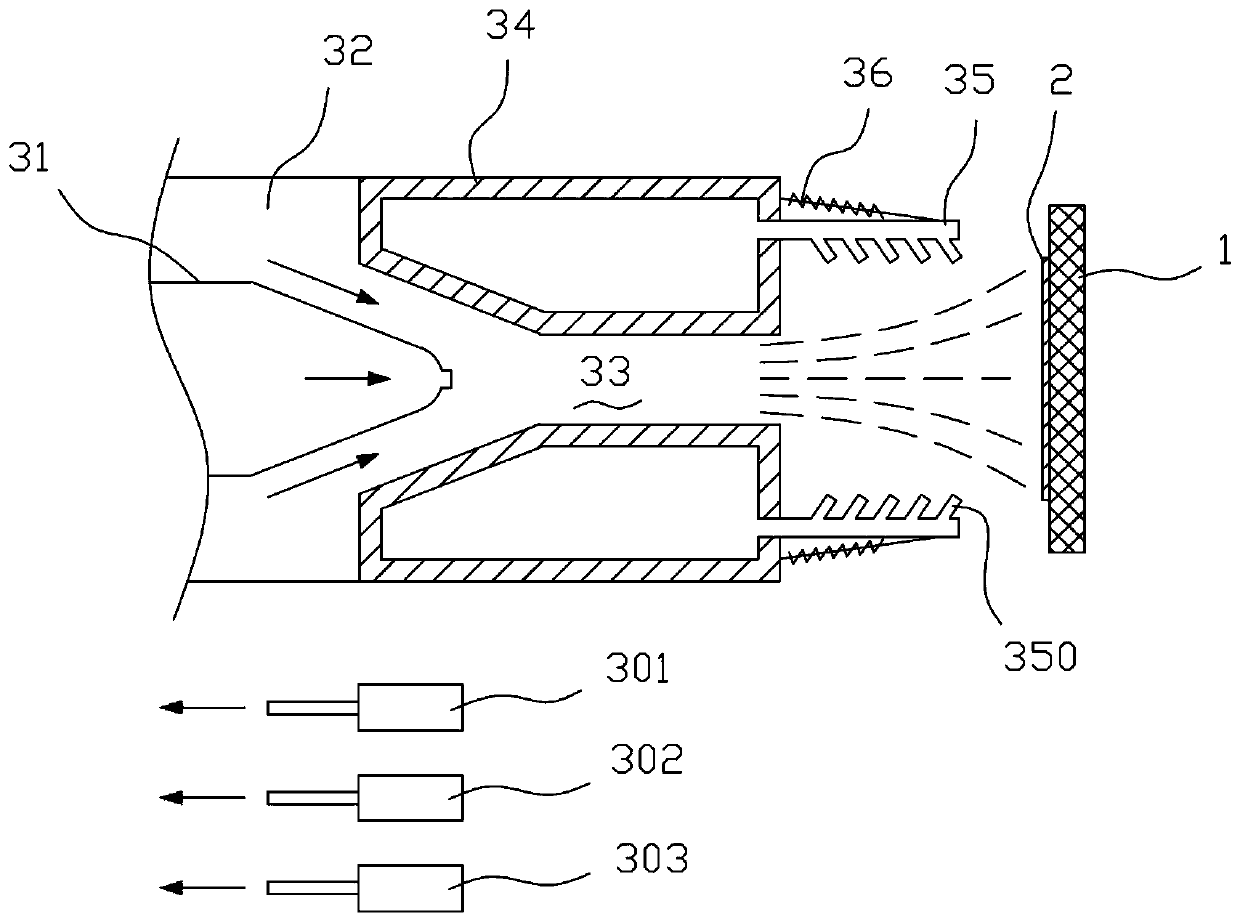
[0029] Such as figure 1 and figure 2 As shown, the present invention provides a kind of spraying device of PTC heating material for toilet seat, it comprises:

[0030] The material supply part 31 is used for storing and exporting the PTC heating material;

[0031] A material blowing part, which is arranged on the side of the material supply part 31, is used to blow the PTC heating material onto the toilet seat 1 to form a PTC heating layer 2;

[0032] Spraying guiding part 35, it is arranged on the side part of the outlet of described material blowing part, is used for guiding the PTC heating material that blows out from described material blowing part, prevents PTC heating material from being sprayed outside the preset range, and is used for drying the PTC heating layer ...


PUM


Abstract

The invention discloses a spraying device for a PTC heating material for a toilet ring. The spraying device comprises a material supply part, a material blowing and conveying part, spraying and guiding parts and a heating element, wherein the material supply part is used for storing and guiding out the PTC heating material. The material blowing and conveying part is used for blowing and conveyingthe PTC heating material to the toilet ring to form a PTC heating layer. The spraying and guiding parts are arranged on the side of an outlet of the material blowing and conveying part and is used forguiding the PTC heating material blown out from the material blowing and conveying part so as to prevent the PTC heating material from being sprayed out of the preset range and used for drying the PTC heating layer. The spraying and guiding parts guide the PTC heating material through cold air. The spraying and guiding parts dry the PTC heating layer through hot air. The heating element is used for heating the cold air into hot air. In the spraying process, the PTC heating material can be effectively prevented from being sprayed out of the preset range, the PTC heating material can also be dried in the spraying process, the spraying efficiency is improved, and incomplete drying of the PTC heating material layer is avoided.

Description

technical field [0001] The invention relates to the technical field of material spraying, in particular to a spraying device and a spraying method of a PTC heating material for a toilet seat. Background technique [0002] The setting of the PTC heating element can heat the toilet seat at a constant temperature, but it will lead to uneven heating temperature of the toilet seat. In order to avoid uneven temperature, people began to try to coat the PTC polymer material on the underside of the toilet seat as a heating layer. [0003] Usually the PTC polymer material is used as the heating layer to spray the PTC polymer material on the lower part of the toilet seat. The spraying efficiency of the conventional spraying device is low, and it is difficult to meet the needs of high-efficiency production; at the same time, the PTC polymer material is easily damaged during the spraying process. Spraying is out of bounds, resulting in the position that should not be sprayed is also cove...

Claims


Application Information

Patent Timeline
IPC IPC(8): B05B12/18B05B16/20B05D3/04B05B7/04B05D1/02
CPCB05B7/04B05D1/02B05D3/0413B05B12/18B05B16/20
Inventor 周荣张小强吴金炳
Owner SUZHOU LUZHIYAO TECH
Learn More