
Gas-shielded infrared welding and staking system

A technology of infrared and welding methods, which is applied to household appliances, other household appliances, household components, etc., and can solve problems such as reduced welding strength

Pending Publication Date: 2020-05-05
DUKANE CORP
View PDF5 Cites 0 Cited by
  • Summary
  • Abstract
  • Description
  • Claims
  • Application Information

AI Technical Summary

Problems solved by technology

The disadvantage of the IR heating method is that the surface of the resulting melt can oxidize or burn, resulting in a reduced weld strength when joining the two parts to be welded together

Method used


Image

  • Gas-shielded infrared welding and staking system
  • Gas-shielded infrared welding and staking system
  • Gas-shielded infrared welding and staking system

Examples


Embodiment Construction

[0018] While the invention will be described in conjunction with certain preferred embodiments, it should be understood that the invention is not limited to these particular embodiments. On the contrary, the invention is intended to cover all alternatives, modifications and equivalent arrangements as may be included within the spirit and scope of the invention as defined by the appended claims.

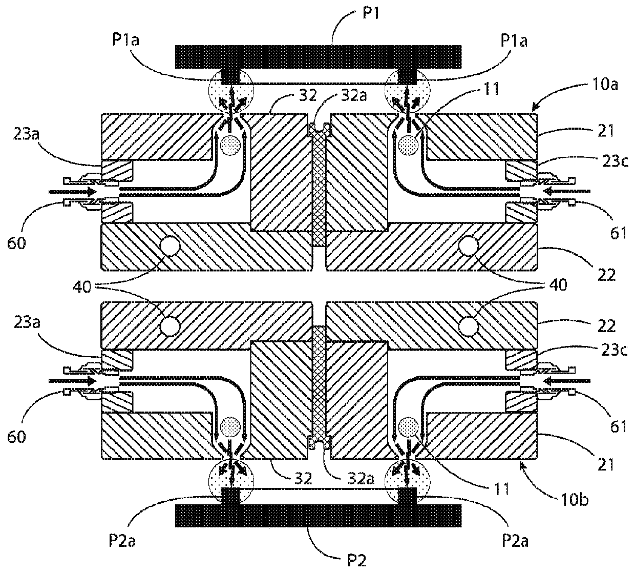
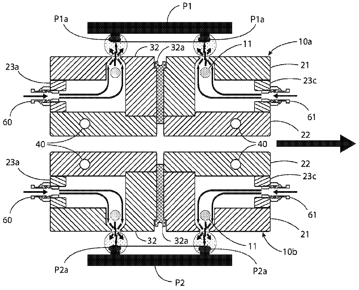
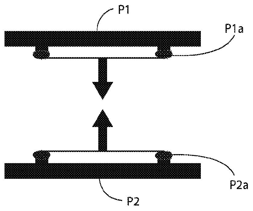
[0019] In the picture, Figure 1 to Figure 9 An IR welding system is shown comprising a pair of identical upper and lower radiant heating units 10a, 10b for heating selected portions of a pair of thermoplastic parts P1 and P2 to be welded to each other. exist figure 1 Among them, the upper heating unit 10a heats the part P1, and the lower heating unit 10b heats the part P2. The heated parts of the parts P1 and P2 are annular ribs P1a and P2a extending outwardly from the surface of the respective parts P1 and P2 towards the respective heating units 10a and 10b. The surfaces of the p...


PUM


Abstract

An infrared welding system for joining two parts (PI, P2) made of thermoplastic material comprises a pair of infrared heaters (11, 11) for heating the two parts (PI, P2) while spaced from each other;and energizing the infrared heaters (11, 11) to emit infrared heat and directing the emitted infrared heat onto selected portions (Pla, P2a) of the opposed surfaces of the parts (PI, P2) to melt at least portions of the opposed surfaces, while directing an inert gas onto the selected portions to prevent ignition of the melted thermoplastic material. The two parts (PI, P2) are clamped together by moving at least one of the parts toward the other part to press the melted surfaces of the parts (PI, P2) into contact with each other. The parts (PI, P2) are cooled while they remain clamped togetherto solidify the molten thermoplastic material and thus weld the two parts (PI, P2) together.

Description

[0001] Cross References to Related Applications [0002] This application claims priority to US Patent Application Serial No. 15 / 707,360, filed September 18, 2017, which is hereby incorporated by reference in its entirety. technical field [0003] The present invention relates generally to the welding of thermoplastic materials and, more particularly, to a gas shielded infrared welding system for welding and riveting thermoplastic materials. Background technique [0004] The present invention generally relates to infrared (IR) welding. More specifically, the present invention relates to the use of IR heaters in the plastics welding industry to melt portions of thermoplastic components that are welded together or riveted together. An example of a practical application of infrared welding is welding together two halves of an automotive plastic intake manifold. Conventional methods of welding such manifolds utilize hot gas heating or infrared (IR) heating [0005] The hot ga...

Claims


Application Information

Patent Timeline
IPC IPC(8): B29C65/14B29K101/12
CPCB29L2031/7492B29C65/103B29C65/1432B29C65/1467B29C65/72B29C66/003B29C66/1142B29C66/24221B29C66/3494B29C66/54B29C66/73921B29C66/8167B29C66/8181B29C66/949B29C65/1412B29C66/00141B29C66/349B29C66/8145
Inventor 保罗·H·卡斯卡特
Owner DUKANE CORP
Learn More