
Method for mapping xml service logic to java service logic

A business logic and business technology, applied in the field of big data, can solve problems such as separation, and achieve the effect of simple system construction, easy maintenance and testing, and easy management and maintenance

Active Publication Date: 2020-05-05
联通(江苏)产业互联网有限公司
View PDF3 Cites 2 Cited by
  • Summary
  • Abstract
  • Description
  • Claims
  • Application Information

AI Technical Summary

Problems solved by technology

[0004] The purpose of the present invention is to provide a method for mapping xml business logic to java business logic, which solves the technical problem of separating business logic from the system in order to cope with the cumbersome online process in development

Method used


Image

  • Method for mapping xml service logic to java service logic
  • Method for mapping xml service logic to java service logic
  • Method for mapping xml service logic to java service logic

Examples


Embodiment Construction

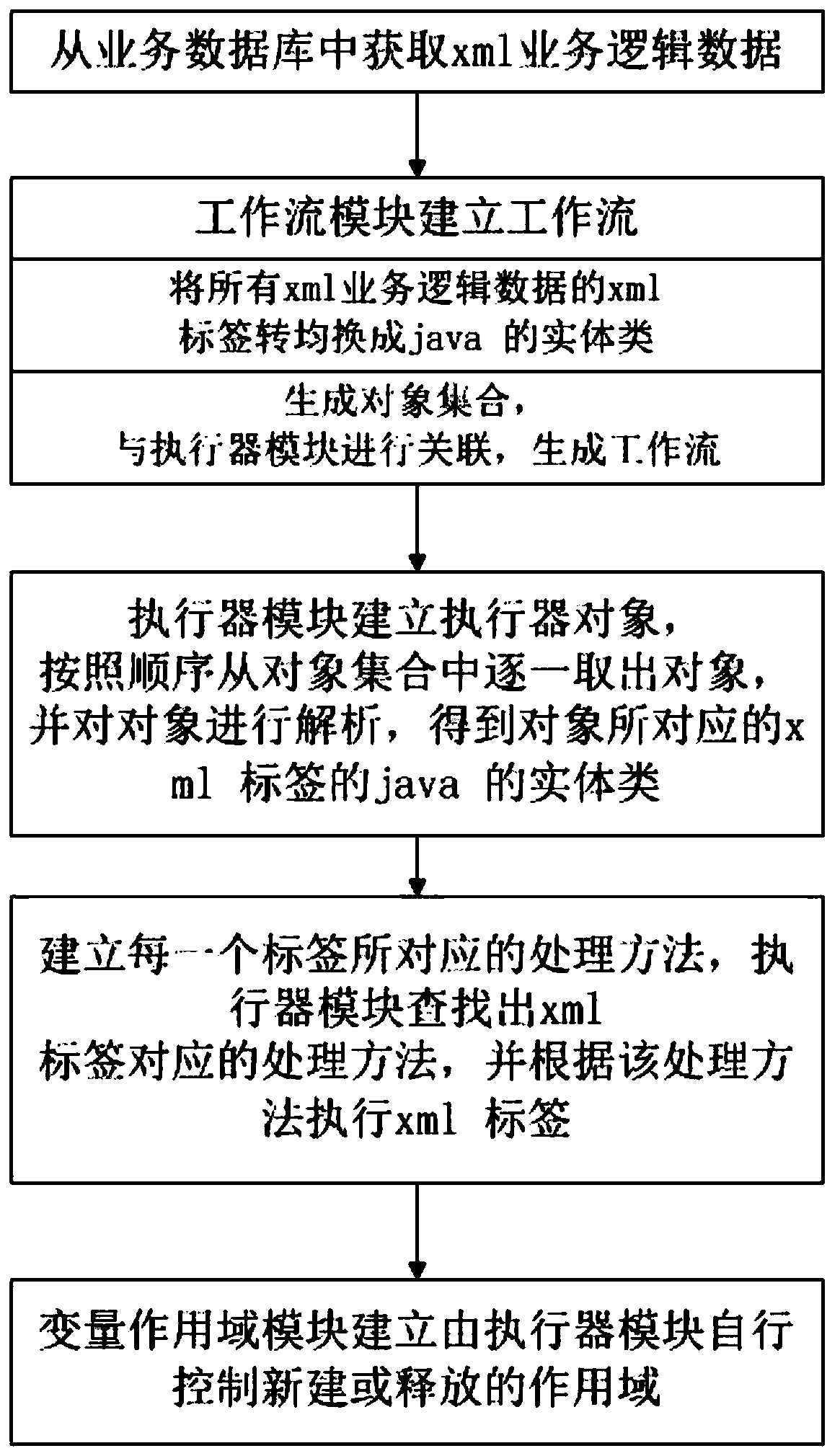
[0026] Such as figure 1 A method for mapping xml business logic to java business logic shown includes the following steps:

[0027] Step 1: Establish a business database and a system center server, the business database is used to store xml business logic data, and the business database and the system center server communicate through the Internet;

[0028] Establish workflow module, executor module and variable scope module in the system center server;

[0029] Step 2: Use the xml tag language in the business database as the description language of the interface logic, each xml business logic data contains an xml tag, and the xml tag includes a start tag and an end tag;

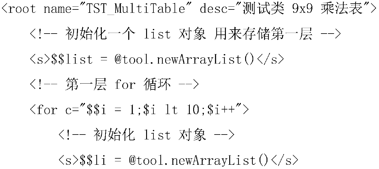
[0030] In this embodiment, take the following test.xml business logic data as an example:

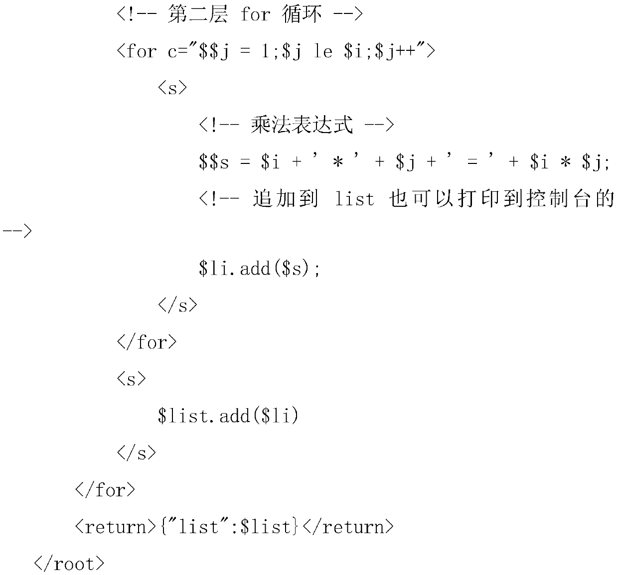
[0031] The content of test.xml business logic data is as follows:

[0032]

[0033]

[0034] The xml business logic data is to output the 99 multiplication table through two for loops.

[0035] Step 3: After...


PUM


Abstract

The invention discloses a method for mapping xml service logic to java service logic, and belongs to the technical field of big data. The method comprises the following steps: establishing a service database and a system center server, wherein the service database is used for storing xml service logic data, and the service database communicates with the system center server through the Internet; and establishing a workflow module, an actuator module and a variable action domain module in a system center server. The technical problem of realizing separation of business logic and a system in order to cope with a tedious online process in development is solved, the system is very simple to build on a small scale and can be realized only by loading a plurality of jar packets, and the service realizes interface management, is easy to maintain and test and is easy to manage and maintain.

Description

technical field [0001] The invention belongs to the technical field of big data, and relates to a method for mapping XML business logic to Java business logic. Background technique [0002] The interface system of an enterprise often needs to be connected to multiple parties and support multiple protocols, and due to the large number of third parties and changes in requirements, a very flexible interface system is required. This interface system needs to meet the requirements, high performance, stability, and easy management. Maintenance, as well as a complete log system and statistical functions. [0003] The logic of the interface system is relatively simple. If a layer of simple abstraction is made, it can be divided into three layers, namely: packet conversion of the receiving side, packet conversion of the outgoing side, and connectors connecting the outgoing side. If only this kind of abstraction is done, as the system becomes larger and larger, it will become more an...

Claims


Application Information

Patent Timeline
Patent Type & Authority Applications(China)
IPC IPC(8): G06F8/51G06F8/30G06F40/151
CPCG06F8/51G06F8/315Y02D10/00
Inventor 丁星
Owner 联通(江苏)产业互联网有限公司
Learn More