
Leveling control system and method for rocket launching platform

A rocket launch platform and control system technology, which is applied in the field of automatic control, can solve problems such as too large leveling accuracy error, economic loss, launch delay, etc., and achieve the effect of precise leveling process

Pending Publication Date: 2020-05-05
BEIJING LANDSPACETECH CO LTD
View PDF9 Cites 12 Cited by
  • Summary
  • Abstract
  • Description
  • Claims
  • Application Information

AI Technical Summary

Problems solved by technology

[0004] First: The traditional one-level two-vertical (horizontal transfer, vertical assembly, and vertical test) and three-vertical (vertical transfer, vertical assembly, and vertical test) mode launch towers are far away from the rocket, and the rocket connector protrudes through the launch tower. The swing arm is connected to the rocket, and the rocket connector also adopts the mode of falling off in advance. The error of the level of the launch platform will not cause a safety risk to the launch process; After the ignition, the vertical arm is quickly reversed to give way to the rocket take-off drift. If the leveling accuracy error is too large, the rocket may hit the vertical arm during take-off, resulting in a major flight accident in which the arrow is destroyed;
[0005] Second: The leveling process of the traditional one-level, two-down and three-down modes is gradually completed during the rocket assembly process, and the leveling process has little impact on the launch process time; the launch pad leveling process under the three-level mode is included in the launch process, The leveling process of the launch pad directly affects the length of the launch process. If the leveling process is too long or the leveling process is unreliable, it will directly lead to the delay or even cancellation of the launch, and will also cause major economic losses.

Method used


Image

  • Leveling control system and method for rocket launching platform
  • Leveling control system and method for rocket launching platform
  • Leveling control system and method for rocket launching platform

Examples


Embodiment Construction

[0027] The characteristics and exemplary embodiments of various aspects of the present invention will be described in detail below. In order to make the purpose, technical solutions and advantages of the present invention clearer, the present invention will be further described in detail below in conjunction with the accompanying drawings and specific embodiments. It should be understood that the specific embodiments described here are only configured to explain the present invention and to exemplify the principle of the present invention, and are not configured to limit the present invention. Additionally, the mechanical components in the figures are not necessarily drawn to scale. For example, the size of some structural components or regions in the drawings may be exaggerated for other structural components or regions, so as to facilitate the understanding of the embodiments of the present invention.

[0028] The orientation words appearing in the following description are ...


PUM


Abstract

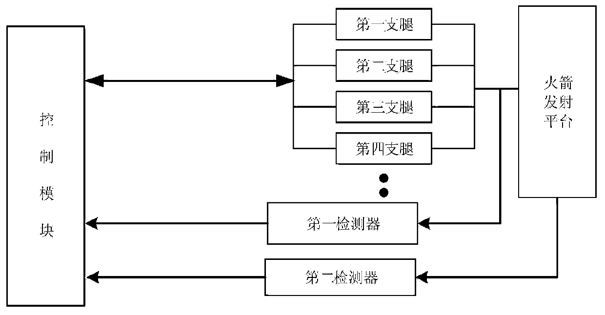
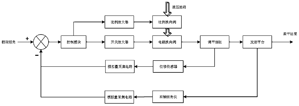
The invention discloses a leveling control system and method for a rocket launching platform. The leveling control system of the rocket launching platform comprises: a first detector arranged on a movable supporting leg of the rocket launching platform and used for feeding back the length of the movable supporting leg; a second detector used for detecting a first inclination angle of the rocket launching platform relative to the first shaft and a second inclination angle of the rocket launching platform relative to the second shaft; and a control module used for calculating the distance needing to be adjusted of the movable supporting leg by utilizing the first inclination angle and the second inclination angle and controlling the movable supporting leg to be adjusted until the platform meets the precision requirement. By means of the leveling control system of the rocket launching platform, leveling of the launching platform can be rapidly and accurately completed, the second detectoris used for judging the inclination angles in the two axial directions, the control module calculates the distance needing to be adjusted of each movable supporting leg, the corresponding distance isadjusted through the first detector, the control module controls the movable supporting legs to be leveled, and the first detector enables the leveling process to be faster and more accurate.

Description

technical field [0001] The invention relates to the technical field of automatic control, in particular to a leveling control system and method for a rocket launch platform where a launch vehicle or special equipment requires a precise leveling environment. Background technique [0002] With the rapid development of my country's aerospace industry, the "three-level" test-launch mode has gradually appeared in the test-launch mode of the launch vehicle. The "three-level" test-launch mode puts forward high requirements on the leveling accuracy and time of the launch pad. [0003] This is reflected in two aspects: [0004] First: The traditional one-level two-vertical (horizontal transfer, vertical assembly, and vertical test) and three-vertical (vertical transfer, vertical assembly, and vertical test) mode launch towers are far away from the rocket, and the rocket connector protrudes through the launch tower. The swing arm is connected to the rocket, and the rocket connector a...

Claims


Application Information

Patent Timeline
IPC IPC(8): G05D3/12F41F3/04
CPCG05D3/12F41F3/04
Inventor 韦银利吴雪张瑜韩召洋张彦杰杨俊
Owner BEIJING LANDSPACETECH CO LTD
Learn More