
Spinning assembly for multi-component fiber

A spinning component and multi-component technology, which is applied in the field of spinning components for multi-component fibers, can solve the problems of reduced core capacity, increased area, and increased volume of the melting cavity, so as to ensure spinning quality and reduce length. Small, to avoid the effect of mutual influence

Pending Publication Date: 2020-05-05
CHANGSHU GOLD SPRING CHEM FIBERS & KNITTINGS
View PDF1 Cites 1 Cited by
  • Summary
  • Abstract
  • Description
  • Claims
  • Application Information

AI Technical Summary

Problems solved by technology

[0003] At present, the melt-spinning two-component spinning assembly usually adopts an inner circle outer ring filter cavity structure in the form of CN108707987A or a layered filter cavity structure. If this type of structure is used to produce multi-component fibers, the following technical problems will occur: due to spinning The significant increase in sealing rings, filter screens and other parts used in the wire assembly will lead to a decrease in the core capacity of the melting chamber; the volume of the annular separation plate between the chamber walls of the different components of the melt will increase, for example, the two-component inner chamber There is an isolating ring between the outer chamber and the outer cavity. For each additional component component, an annular isolating plate needs to be added. The length of the annular isolating plate between the two melting cavities is the circumference of the isolating ring. The melt temperature of the components is different, and the increase of the partition area means that the area where the two melt temperatures affect each other will be correspondingly increased
Typical polylactic acid fiber materials and polyester fiber materials produce multi-component fibers. Due to the large difference in melting temperature of the two materials, the increase in the area of ​​the partition in the spinning assembly will cause the melts on both sides of the partition to affect each other. The area increases, which is very unfavorable for the control of spinning quality
Therefore, the problem of how to reasonably reduce the area of ​​the partitions used to separate the melting chamber has been perplexing the industry for a long time and is expected to be solved. However, there is no technical inspiration that can be used for reference in the Chinese and foreign patents and non-patent literature published so far. The following The technical solution to be introduced is produced under this background

Method used


Image

  • Spinning assembly for multi-component fiber
  • Spinning assembly for multi-component fiber
  • Spinning assembly for multi-component fiber

Examples


Embodiment Construction

[0020] In order to understand the technical essence and beneficial effects of the present invention more clearly, the applicant will describe in detail the following examples, but the descriptions of the examples are not intended to limit the solutions of the present invention. Equivalent transformations that are only formal but not substantive should be regarded as the scope of the technical solution of the present invention.

[0021] In the following descriptions, all concepts related to directionality or orientation of up, down, left, right, front and back are based on figure 1 The current position is a reference, so it cannot be understood as a special limitation on the technical solution provided by the present invention.

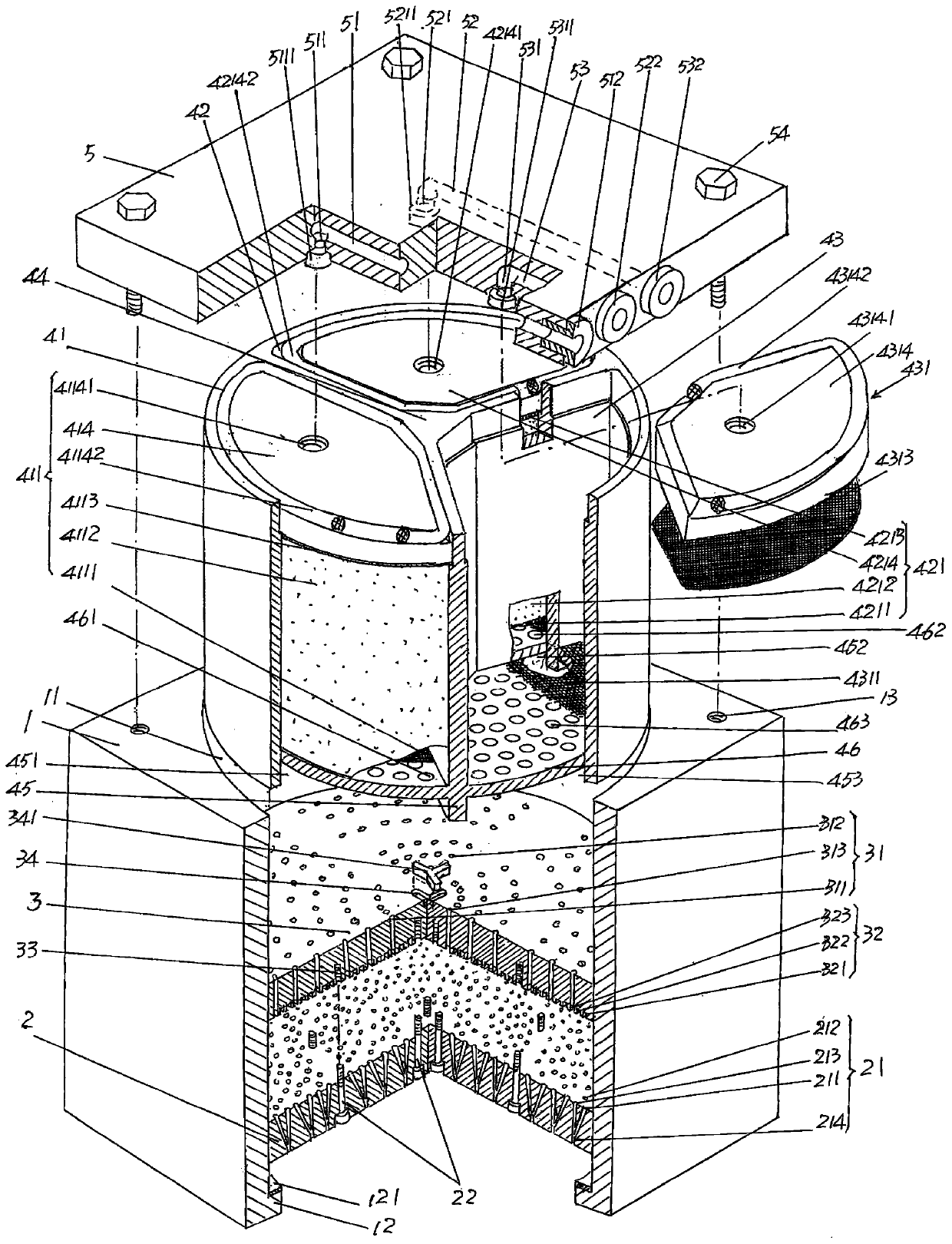
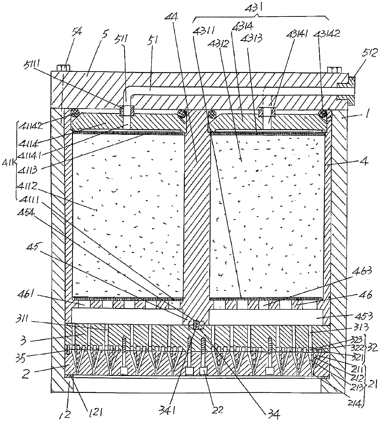
[0022] See figure 1 , shows a box 1 whose exterior is rectangular and specifically rectangular parallelepiped (but can also be a cube); shows a spinneret 2, which is arranged on the circular The bottom of the box cavity 11 is provided with a spinnere...


PUM


Abstract

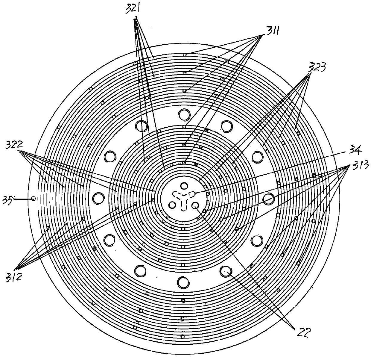
The invention discloses a spinning assembly for a multi-component fiber, and belongs to melt spinning equipment. The spinning assembly comprises a box body, a spinneret plate, a melt distribution plate, a melt filtering cylinder and a box body cover, wherein the spinneret plate is arranged at the bottom of a box body cavity, and spinneret plate capillary spinneret holes are formed in the spinneretplate; the melt distribution plate is stacked above the spinneret plate, and is provided with melt distribution holes, and a melt distribution groove is formed in the bottom of the melt distributionplate; the melt filtering cylinder is arranged in the box body cavity and is supported on the melt distribution plate, and comprises a first melt filtering cavity, a second melt filtering cavity and athird melt filtering cavity; the box body cover is fixed with the top surface of the box body, and the box body cover is provided with a first component melt lead-in hole, a second component melt lead-in hole and a third component melt lead-in hole; the left end of the first component melt lead-in hole communicates with the upper part of the first melt filtering cavity; the left end of the secondcomponent melt lead-in hole communicates with the upper part of the second melt filtering cavity; the left end of the third component melt lead-in hole communicates with the upper part of the third melt filtering cavity; and the first component melt lead-in hole, the second component melt lead-in hole and the third component melt lead-in hole extend into the right side surface of the box body cover and communicate with the outside. Mutual influence caused by different component melt temperatures can be avoided, and the spinning quality is ensured.

Description

technical field [0001] The invention belongs to the technical field of melt spinning equipment, and in particular relates to a spinning assembly for multi-component fibers. Background technique [0002] The multi-component mentioned above mainly refers to three components, but not limited to three components, for example, there may be more components such as four components or even five components. As known in the industry, due to the different arrangement of the components, the bicomponent fibers can make the fibers have different characteristics. For example, the side-by-side bicomponent fibers have a three-dimensional self-crimping effect. Another example is that the skin-core fiber has a skin that is wear-resistant and has a good skin feel, while the core has the characteristics of high strength and can greatly enrich the variety of textile fabrics. The above-mentioned three-component or even more-component fibers can further improve the fiber function, but at the same ...

Claims


Application Information

Patent Timeline
Patent Type & Authority Applications(China)
IPC IPC(8): D01D5/30D01D1/10
CPCD01D1/106D01D5/30
Inventor 樊慧斌杜祎新张志刚昝丽琴朱振江
Owner CHANGSHU GOLD SPRING CHEM FIBERS & KNITTINGS
Learn More