
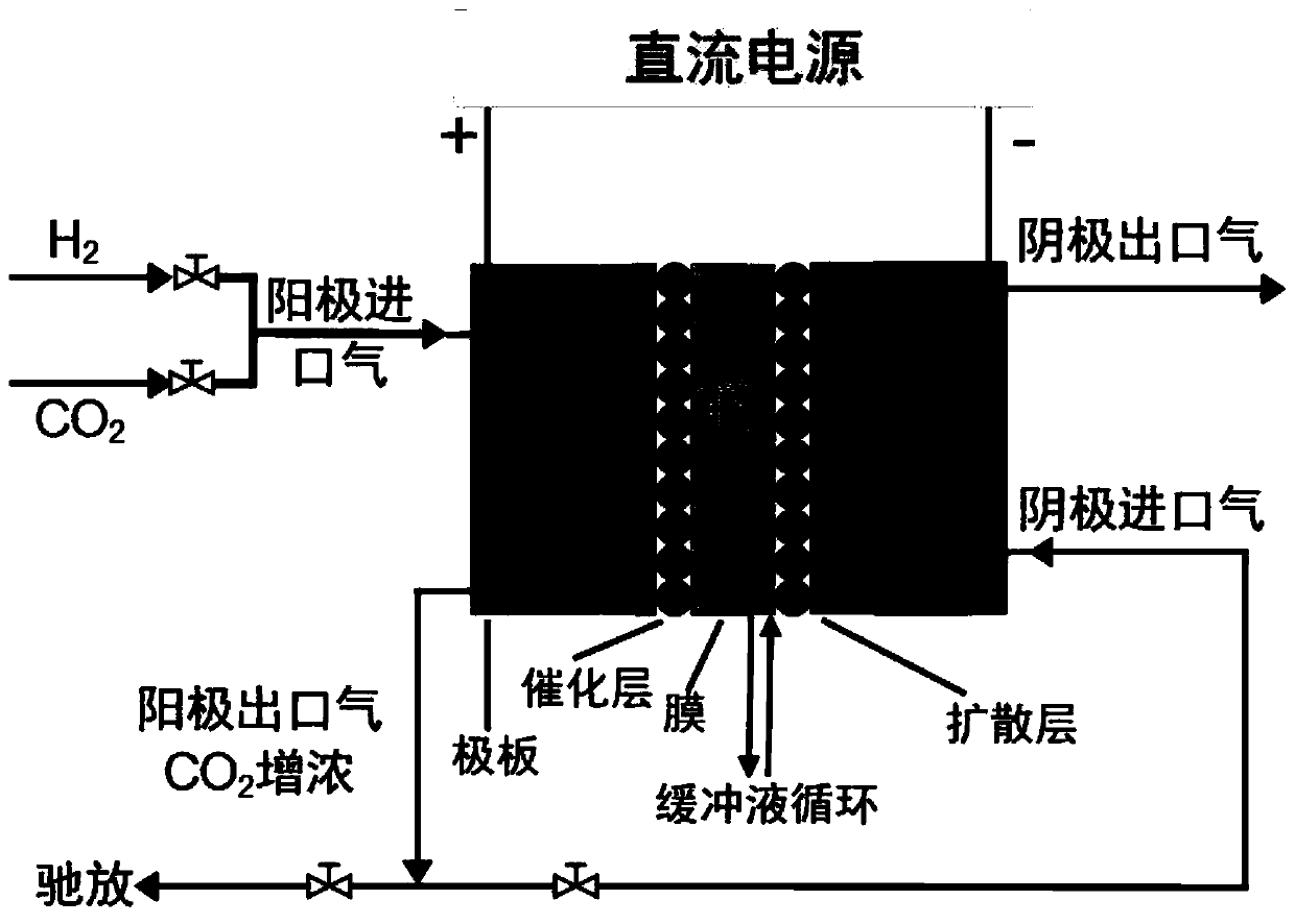
H2/CO2 separation and CO2 hydrogenation self-coupling method

A CO2 and self-coupling technology, applied in the field of electrochemical engineering, can solve the problems of lack of reference in the design of electrochemical hydrogen pump coupling process, and achieve the effects of improving safety and operability, reducing costs, and reducing material consumption

Active Publication Date: 2020-05-05
DALIAN UNIV OF TECH
View PDF2 Cites 3 Cited by
  • Summary
  • Abstract
  • Description
  • Claims
  • Application Information

AI Technical Summary

Problems solved by technology

But none of the above methods achieve H 2 / CO 2 Separation and CO 2 The hydrogenation is carried out at the same time, and there is no reference for the design of the electrochemical hydrogen pump coupling process in which the anode and cathode can use the same raw material

Method used


Image

  • H2/CO2 separation and CO2 hydrogenation self-coupling method
  • H2/CO2 separation and CO2 hydrogenation self-coupling method
  • H2/CO2 separation and CO2 hydrogenation self-coupling method

Examples


Embodiment 1

[0022] In the electrochemical hydrogen pump reactor, the anode is hydrogen-containing CO with a hydrogen gas integration rate of 20%. 2 Mixed gas feed, the feed amount is 20sccm; the buffer solution is KHCO with a concentration of 0.5mol / L 3 , The circulation flow rate is 15mL / min, and the cathode catalyst loading capacity is 2mg / cm 2 , the anode catalyst loading is 0.5mg / cm 2 , the anode outlet adopts zero discharge to pass all the outlet gas into the cathode, and the flow rate is 18 sccm. When the electrochemical hydrogen pump reactor with a constant current of 30mA / cm 2 , After 30min at 25°C, the cathode potential is -1.25V, CO 2 The reaction rate of hydrogenation to form formic acid is 70.5mmol / (s cm 2 ), the current efficiency is 57.5%, CO 2 The conversion rate of 4.0%, H 2 The utilization rate was 16.0%.

Embodiment 2

[0024] In the electrochemical hydrogen pump reactor, the anode is hydrogen-containing CO with a hydrogen gas integration rate of 75%. 2 Mixed gas feed, the feed amount is 25 sccm, the buffer solution is KHCO with a concentration of 1.5mol / L 3 , The circulation flow rate is 10mL / min, and the cathode catalyst loading capacity is 1.5mg / cm 2 , the anode catalyst loading is 0.2mg / cm 2 , the anode outlet adopts zero discharge to pass all the outlet gas into the cathode, and the flow rate is 20 sccm. When the electrochemical hydrogen pump reactor with a constant current of 3mA / cm 2 , After running at 25°C for 30 minutes, the cathode potential is -0.74V, CO 2 The reaction rate of hydrogenation to form formic acid is 10.4mmol / (s cm 2 ), the current efficiency is 42.8%, CO 2 The conversion rate of H 2 The utilization rate is 0.75%.

Embodiment 3

[0026] In the electrochemical hydrogen pump reactor, the anode is hydrogen-containing CO with a hydrogen gas integration rate of 33.3%. 2 Mixed gas feed, the feed amount is 5 sccm; the buffer solution is KHCO with a concentration of 2.5mol / L 3 , The circulation flow rate is 12mL / min, and the cathode catalyst loading capacity is 3mg / cm 2 , the anode catalyst loading is 0.4mg / cm 2 , a part of the anode outlet is discharged, and a part is passed into the cathode, and the flow rate is 1 sccm. When the electrochemical hydrogen pump reactor with a constant current of 18.9mA / cm 2 , After 30min at 25°C, the cathode potential is -1.31V, CO 2 The reaction rate of hydrogenation to form formic acid is 27.1mmol / (s cm 2 ), the current efficiency is 27.6%, CO 2 The conversion rate was 6.5%, and the hydrogen utilization rate was 13.1%.


PUM


Abstract

The invention belongs to the technical field of electrochemical engineering, and relates to a H2 / CO2 separation and CO2 hydrogenation self-coupling method. In an electrochemical hydrogen pump, H2 / CO2mixed gas is fed from an anode, anode outlet gas is introduced into a cathode to serve as a raw material, and cathode CO2 hydrogenation is achieved. When electric energy is externally added at normaltemperature and normal pressure, high selectivity and controllable dissociation of the hydrogen at the anode are realized by utilizing an extremely low electrochemical window of hydrogen, and generated hydrogen protons are transferred to a cathode catalyst layer to generate in-situ adsorption hydrogen to participate in cathode CO2 hydrogenation. CO2 in the anode outlet mixed gas is enriched through hydrogen transmembrane transmission and is directly used as cathode feed, so that cathode CO2 catalytic hydrogenation is realized. According to the invention, hydrogen separation and CO2 hydrogenation of the same strand of H2 / CO2 feed gas are synchronously carried out in the same reactor, and synergistic interaction is realized, so that the process and the device are simplified, and the utilization rate of the H2 / CO2 feed gas is improved.

Description

technical field [0001] The invention belongs to the technical field of electrochemical engineering and relates to a H 2 / CO 2 Separation and CO 2 Hydrogenation self-coupling method. Background technique [0002] CO 2 It is a greenhouse gas and a C1 raw material with abundant reserves and low cost. In recent years, atmospheric CO 2 Concentrations have increased dramatically, while about 50% of them come from emissions from the petrochemical industry. Therefore, the CO in petrochemical tail gas 2 Capturing and transforming is of great significance to solving the global greenhouse effect and energy crisis. The main component of many petrochemical tail gases is H 2 and CO 2 , if calculated by volume fraction, the hydrogen contained in the PSA tail gas from natural steam reforming 2 42%, CO 2 37%; Coal gasification hydrogen product contains H 2 56%, CO 2 41%; hydrogen production PSA desorption gas contains H 2 25%, CO 2 50% etc. Take full advantage of these h...

Claims


Application Information

Patent Timeline
IPC IPC(8): C25B3/00C07C53/02C01B3/50
CPCC25B3/00C07C53/02C01B3/50
Inventor 吴雪梅金锐贺高红阮雪华肖武李祥村姜晓滨范姝艾程慧远方远鑫鲍志贤严鑫艺
Owner DALIAN UNIV OF TECH
Learn More