Dust suction device for stone machining

A dust collection device and stone processing technology, applied in stone processing equipment, processing models, decorative art, etc., can solve the problems of internal blockage, a large amount of dust, and ingress of the device, so as to facilitate collection, reduce friction, and speed up flow speed effect

Inactive Publication Date: 2020-05-05
周庆祥
View PDF1 Cites 1 Cited by
  • Summary
  • Abstract
  • Description
  • Claims
  • Application Information

AI Technical Summary

Problems solved by technology

The dust-cleaning and dust-absorbing device of a stone engraving machine in the above-mentioned patent has the following disadvantages: a large amount of dust will be generated when the stone is processed, and when the existing device absorbs the dust, a large amount of dust will be concentrated due to suction together into the interior of the device, which may cause blockage of the interior of the device

Method used


Image

  • Dust suction device for stone machining
  • Dust suction device for stone machining
  • Dust suction device for stone machining

Examples


Embodiment 1

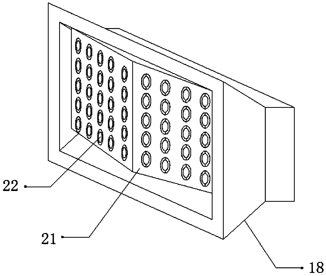
[0029] refer to Figure 1-3 , a dust collection device for stone processing, comprising a fixed seat 1, the four corners of the top outer wall of the fixed seat 1 are connected with a spring 4 by bolts, and the top outer wall of the spring 4 is connected with a dust collection box 5 by bolts, the top of the fixed seat 1 The outer wall is connected with the impact block 2 by bolts, and the outer wall of one side of the dust collection box 5 is provided with a dust inlet, and the inner wall of the dust inlet is connected with a dust inlet pipe 17 by bolts, and the outer wall of one side of the dust inlet pipe 17 is connected by a flange. Fan 19 is arranged, and one side outer wall of fan 19 is provided with air duct 20, and one side outer wall of air duct 20 is connected with dust collection cover 18 by bolt, and the inwall of dust collection cover 18 is connected with splitter plate 21 by bolt, splitter plate The outer walls on both sides of 21 are provided with a plurality of ...

Embodiment 2

[0040] refer to Figure 4 , a dust collection device for stone processing. Compared with Embodiment 1, the inner wall of the collection box 6 is connected with a filter screen 24 through hinges in this embodiment, which can purify the dust.

[0041]Working principle: When in use, move the device to a suitable position through the moving wheel 3 and the push rod 9, start the fan 19, the fan 19 will absorb the dust into the interior of the dust collection hood 18, and the dust will enter the interior of the dust inlet 22 , so as to enter the inside of the dust collection box 5 through the dust inlet pipe 17, inject an appropriate amount of water into the inside of the water tank 12 through the water inlet, and deliver the water to the inside of the catheter tube 10 through the drain pipe 13 and the solenoid valve 14, thereby passing The atomizing nozzle 15 sprays out the water mist so that the dust can be dust-reduced. The dust will enter the inside of the collection box 6 throu...


PUM


Abstract

The invention discloses a dust suction device for stone machining. The dust suction device comprises a fixed seat; springs are fixed at the four corners of the outer wall at the top of the fixed seat;a dust suction box is fixed to the outer wall at the top of the spring; an impact block is fixed to the outer wall at the top of the fixed seat; a dust inlet is formed in the outer wall on one side of the dust suction box; a dust inlet pipe is fixed to the inner wall of the dust inlet; the outer wall of one side of the dust inlet pipe is connected with a fan through a flange; an air pipe is arranged on the outer wall of one side of the fan; a dust suction cover is fixed to the outer wall of one side of the air pipe; shunt plates are fixed to the inner wall of the dust suction cover; and a plurality of dust inlets are formed in the outer walls of the two sides of the shunt plates. The blockage of the interior of the dust suction device caused by dust concentration can be prevented, the backflow of the dust in the dust suction device can be prevented, the situation that the dust adheres to the inner wall of the dust suction device to affect the collection of the dust can be prevented, and the situation that the collection of the dust is affected since a collection box is worn due to large friction force can be prevented.

Description

technical field [0001] The invention relates to the technical field of stone processing, in particular to a dust suction device for stone processing. Background technique [0002] As a high-grade building decoration material, stone is widely used in indoor and outdoor decoration design, curtain wall decoration and public facilities construction. At present, the common stone materials in the market are mainly divided into natural stone, artificial stone and marble. When processing stone, it needs to be vacuumed The device collects the dust generated during processing to prevent the dust from being discharged to the outside and causing environmental pollution. [0003] After retrieval, the Chinese patent authorization number is CN208946956U, which discloses a dust-absorbing device for a stone engraving machine, including a body. Support block, the support block is slidingly engaged with the body, the top of the support block is fixedly connected with a beam, the fronts of the...

Claims


Application Information

Patent Timeline
Patent Type & Authority Applications(China)
IPC IPC(8): B28D7/02B44B1/06B44B3/06
CPCB28D7/02B44B1/06B44B3/06
Inventor 周庆祥
Owner 周庆祥
Why Eureka
Try Eureka