
Biosensor

A biosensor and sensor body technology, applied in the field of biosensors with multi-electrode structure, can solve the problems of difficult implantation of sensors into the body, no way to achieve experience, and implantation of sensors into subcutaneous or tissue fluid layers, etc., so as to improve test accuracy and solve detection problems. Accuracy and wearing experience, the effect of increasing the number

Pending Publication Date: 2020-05-05
上海硕创生物医药科技有限公司
View PDF0 Cites 1 Cited by
  • Summary
  • Abstract
  • Description
  • Claims
  • Application Information

AI Technical Summary

Problems solved by technology

[0005] Due to the limitation of the chemical induction coating, the existing biosensors can only be processed into single-sided electrodes. The consequence of this is that when the electrodes are working, in order to meet the requirements of the electrode induction signal, the effective sensing area of ​​the sensor needs to reach a certain value.
However, considering the wearing experience of bio-sensing, the smaller the area, the better the wearing experience, so there is a conflict between wearing experience and detection accuracy
Most of the existing sensors are looking for a balance between detection accuracy and wearing experience. There is no way to achieve a good experience or even a senseless wearing while having high-precision sensing capabilities.
On the other hand, the larger the number of sensor electrodes, the larger the size of the sensor will be, and the longer the sensor will bring certain difficulties to the sensor implantation.
[0006] At present, glucose biosensors are widely used in clinical practice. Glucose testing is usually divided into two types: in vitro and in vivo. Among them, the common blood glucose test strips are used for in vitro testing. Currently, several manufacturers have different solutions for in vivo testing, but without exception. Both need to implant the sensor under the skin or in the interstitial fluid layer

Method used


Image

  • Biosensor
  • Biosensor
  • Biosensor

Examples


Embodiment 1

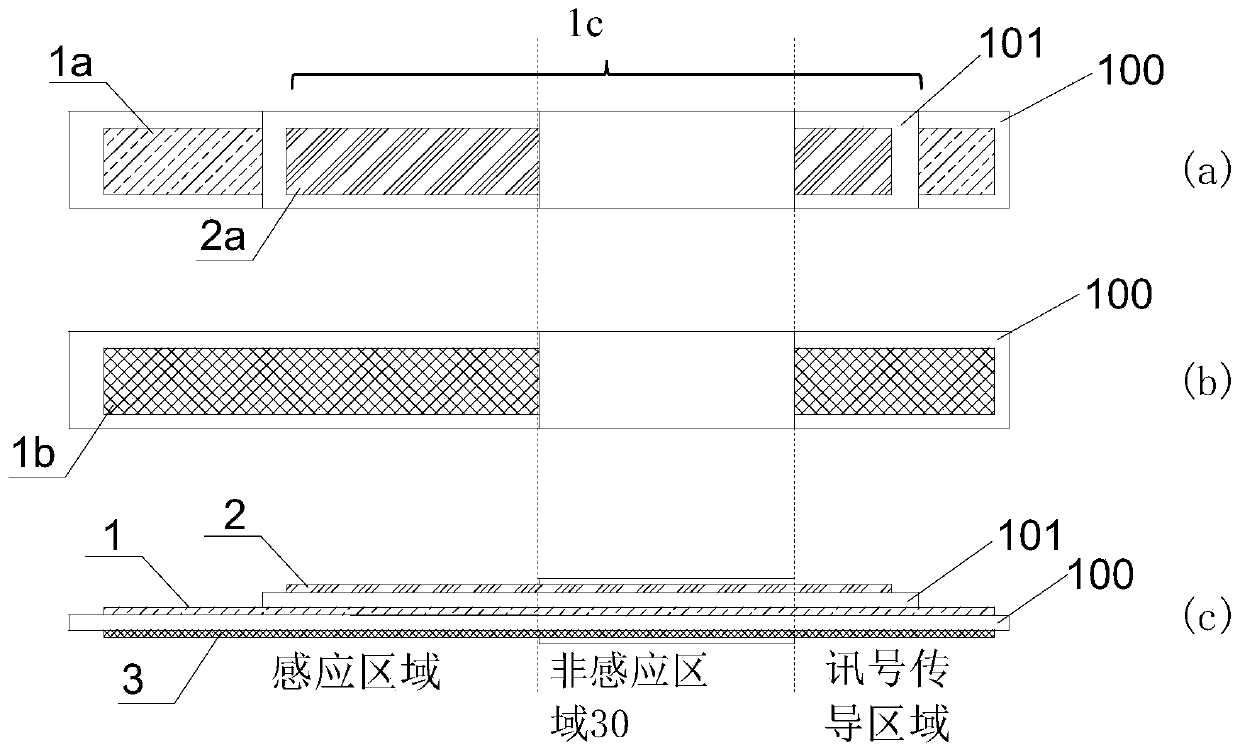
[0051] This embodiment provides a sensor with a three-electrode structure for testing blood sugar levels, and the sensor has a flat structure. Including the sensor body 100, the sensor body 100 includes two physical surfaces, each of which is provided with a functional electrode, the physical surface of the sensor body 100 also includes a non-sensing area, one of which is also provided with a non-sensing area There is another functional electrode. Each of the functional electrodes is provided with a corresponding signal conduction area, and each of the functional electrodes is connected to the corresponding signal conduction area. see figure 1 , figure 1 (a) is the top view of the sensor of the present embodiment, figure 1 (b) is the bottom view of the sensor of the present embodiment, figure 1 (c) is a side view of the sensor of this embodiment.

[0052] Specifically, both physical surfaces of the sensor body 100 are provided with base electrodes (ie metal conductors), a...

Embodiment 2

[0064] This embodiment provides a sensor with a three-electrode structure, see Figure 4 , Figure 4 (a) is the top view of the sensor of the present embodiment, Figure 4 (b) is the bottom view of the sensor of the present embodiment, Figure 4 (c) is a side view of the sensor of this embodiment. The sensor of this embodiment includes a flat sensor body 100, the sensor body 100 includes two physical surfaces, one of the physical surfaces is provided with two base electrodes along the axial direction of the sensor, including the first base electrode located at the head end of the sensor body 100 1a and the second base electrode 2a arranged along the axial direction of the sensor, another physical surface of the sensor body 100 is provided with a third base electrode 3a, the first base electrode 1a, the second base electrode 2a and the third base electrode 3a on the head The ends are coated with corresponding chemical coatings to form working electrode 1, reference electrode...

Embodiment 3

[0068] This embodiment provides a biosensor with a four-electrode structure for testing blood sugar, see Figure 5 , Figure 5 (a) is the top view of the sensor of the present embodiment, Figure 5 (b) is the bottom view of the sensor of the present embodiment, Figure 5 (c) is a side view of the sensor of this embodiment. The structure of the biosensor is similar to the structure of Example 1, the difference is that the non-sensing area of ​​the other physical surface of the sensor body 100 is also provided with a second insulating substrate 102, the first insulating substrate 101 , The second insulating substrate 102 is separately provided on the two physical surfaces of the sensor body 100 , so that the head end of the sensor forms a stepped structure.

[0069] In this embodiment, the base electrode 2b is provided on the second insulating substrate 102, coated with a corresponding chemical coating, and an interference electrode 4 is formed to remove the influence of some...


PUM


Abstract

The invention discloses a biosensor. The biosensor includes a sensor body, wherein the sensor body includes a plurality of physical surfaces, each physical surface is provided with at least one functional electrode, and the physical surface further includes a non-sensing area; and the non-sensing area of at least one of the physical surface is further provided with the other functional electrode,each of the functional electrodes is provided with a corresponding signal conducting area, and each of the functional electrodes is connected with the corresponding signal conducting area. According to the biosensor, since the multiple functional electrodes are distributed on the multiple physical surfaces of the sensor, the length of the sensor can be shortened effectively through the design on the premise of the same sensing area of the sensor; and when the biosensor is compared with a sensor with electrodes which are arranged on one side of the sensor, the length can be shortened by 50% through the design under ideal conditions, and meanwhile the test precision of the sensor can be improved further, so that the problem of contradiction between the test precision and wearing experience of an existing sensor is solved.

Description

technical field [0001] The invention relates to a biosensor, in particular to a biosensor with a multi-electrode structure. Background technique [0002] Biosensors are sensors used to detect corresponding organic or inorganic molecules in body fluids. Biosensors selectively recognize biomolecules, and then the biomolecules and sensors are converted into corresponding current or voltage signals. The concentration and conversion of the substance The strength of the signal has a corresponding mathematical relationship, and the mathematical relationship of strong correlation can be established by mathematical methods, and then the concentration of the substance can be calculated through the size of the signal. [0003] Biosensors are mainly used to detect the physiological indicators of the human body. According to the different physiological indicators detected, the sensors are mainly current-sensing and voltage-sensing. No matter what kind of sensor, its functional compositio...

Claims


Application Information

Patent Timeline
Patent Type & Authority Applications(China)
IPC IPC(8): A61B5/1486G01N27/327
CPCG01N27/3272A61B5/14532A61B5/14546A61B5/1451A61B5/14865G01N27/327A61B2562/164A61B2562/16
Inventor 姚修权
Owner 上海硕创生物医药科技有限公司
Learn More