Electric potato slicer
A slicing machine and potato technology, applied in metal processing and other directions, can solve the problems of easy to cut potatoes, different thicknesses of potatoes, and inability to guarantee the efficiency and quality of manual potato cutting, and achieve uniform slicing and high slicing efficiency. Effect
- Summary
- Abstract
- Description
- Claims
- Application Information
AI Technical Summary
Problems solved by technology
Method used
Image
Examples
Embodiment 1
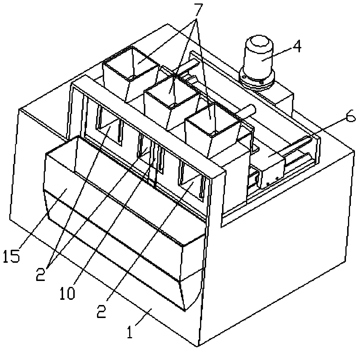
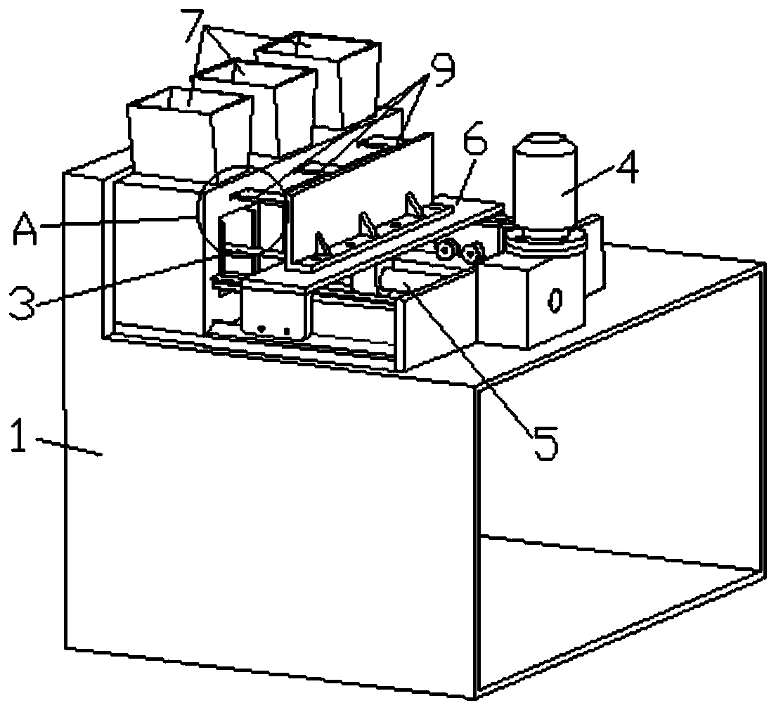
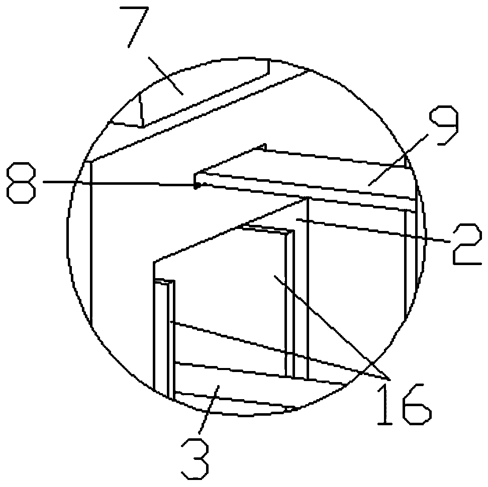
[0037] On the basis of the above structure, in this embodiment, the pushing device includes a drive assembly and at least one push rod 3 corresponding to the silo 2, and the push rod 3 is horizontally slidably installed at one end of the corresponding silo 2; the drive assembly is fixedly installed On the top of the box 1 and at one end of the silo 2, it is fixedly connected with one end of the push rod 3 and drives the push rod 3 to slide horizontally so that the other end extends into the silo 2 to push the potatoes from the silo 2 to the other end. After the potatoes to be sliced are placed in the bin 2, the push rod 3 is driven by the drive assembly to push the potatoes in the bin 2 from one end to the other end. The structure is simple, the degree of automation is high, and time and effort are saved.
[0038] Preferably, in this embodiment, the other end of the push rod 3 is fixedly connected with a vertically arranged push plate, and one side of the push plate is direc...
Embodiment 2
[0041] On the basis of Embodiment 1, in this embodiment, the drive assembly includes a motor one 4 and a lead screw 5, and the motor one 4 is fixedly installed on the top of the box body 1 by bolts, and on the casing of the motor one 4 and the box body 1 The top is respectively provided with the threaded hole that cooperates with bolt; During the potato pushing process, the motor 1 4 drives the lead screw 5 to rotate, and drives the push rod 3 to slide horizontally, so as to push the potatoes from one end of the silo 2 to the other end. The structure is simple, the degree of automation is high, and time and effort are saved.
Embodiment 3
[0043]On the basis of Embodiment 2, in this embodiment, the lead screw 5 is threadedly connected with a nut, the nut is fixedly sleeved with a guide plate 6, and the guide plate 6 is slidably connected to the top of the box body 1. The guide plate 6 is preferably an inverted U The inverted U-shaped guide plate is erected above the lead screw 5, the center of its top is welded together with the nut on the lead screw 5, and the two ends of the bottom are respectively slidingly connected with the top of the box body 1. The top of the body 1 is provided side by side with two guide rails that cooperate with the two ends of the bottom of the inverted U-shaped guide plate. The two ends of the inverted U-shaped guide plate are respectively matched with the guide rails through rollers. The top of the top is vertically fixedly connected with a fixed plate, and one end of the push rod 3 is fixedly connected (welded) with the fixed plate, and the above-mentioned fixed plate is fixedly conn...
PUM
 Abstract
Description
Claims
Application Information
 - R&D Engineer
- R&D Manager
- IP Professional
- Industry Leading Data Capabilities
- Powerful AI technology
- Patent DNA Extraction
Browse by: Latest US Patents, China's latest patents, Technical Efficacy Thesaurus, Application Domain, Technology Topic, Popular Technical Reports.
© 2024 PatSnap. All rights reserved.Legal|Privacy policy|Modern Slavery Act Transparency Statement|Sitemap|About US| Contact US: help@patsnap.com


