
Damping type uncoiler

An uncoiler and damping technology, which is applied in the field of uncoilers, can solve the problems of heavy head, affecting stamping accuracy, and large driving inertia.

Inactive Publication Date: 2020-05-01
丁伟峰
View PDF0 Cites 1 Cited by
  • Summary
  • Abstract
  • Description
  • Claims
  • Application Information

AI Technical Summary

Problems solved by technology

[0003] For conventional equipment, the central axis of the uncoiler head is the center of rotation, and the drive motor directly drives the central axis through the pulley, and then drives the uncoiler head to rotate; such a driving method leads to a large driving inertia, and because the steel coil is loaded , the entire machine head will be very heavy, resulting in a very obvious driving discontinuity, and it cannot be stopped in time, resulting in the output strip being too long and drooping, which will affect the subsequent stamping accuracy

Method used


Image

  • Damping type uncoiler

Examples


Embodiment Construction

[0011] The present invention will be further described below in conjunction with specific embodiments.

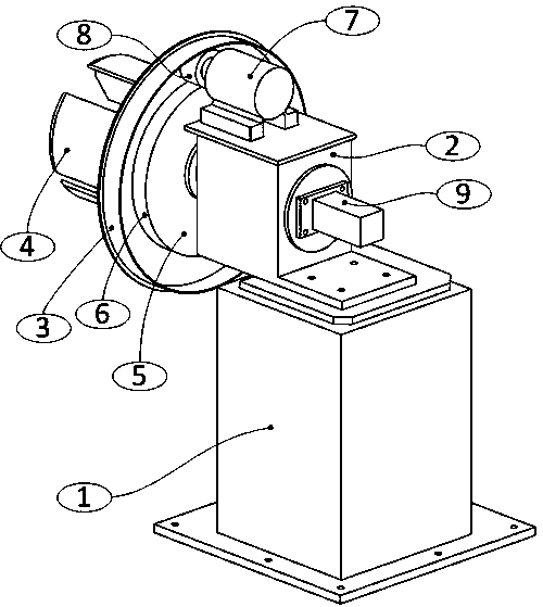
[0012] Such as figure 1 As shown, it is a structural schematic diagram of a damping type uncoiler of the present invention, including a support base 1, which is set at a certain height as required, so that after the strip steel coil is erected on the machine, it can be suspended from the ground, and the There is a control system; a bearing support seat 2 is provided on the support base 1, and the uncoiler head 3 is fixed on the bearing support seat 2 through the rotating bearing support system; the uncoiler head 3 has an expansion-opening type The claw system 4 fixes the strip steel coil to be processed through the opening and closing of the claw system 4 .

[0013] The difference of the present invention is that, on the back side of the uncoiler head 3, a drive disc 5 is arranged, and the drive disc 5 is closely connected with the uncoiler head 3 and rotates synchronously...


PUM

PropertyMeasurementUnit
Depthaaaaaaaaaa

Abstract

The invention discloses a damping type uncoiler. The damping type uncoiler comprises a supporting base, a bearing supporting base is arranged on the supporting base, an uncoiler head is fixed to the bearing supporting base through a rotating bearing supporting system, an expanding type clamping jaw system is arranged on the uncoiler head, a driving plate is arranged on the back face of the uncoiler head, the driving plate and the uncoiler head are tightly connected and rotate synchronously, the driving plate is provided with a driving surface, the driving surface is a steel round surface, a driving motor is arranged on the bearing supporting base, a driving head is arranged on an output shaft of the driving motor, the driving head matches with the driving surface, the driving head is a rubber cylindrical head, is tightly pressed on the driving surface and drives the driving plate to rotate through friction force, and then the whole uncoiler head is driven to rotate. The damping type uncoiler is simple in structure, capable of providing driving force and damping force at the same time and good in using effect.

Description

technical field [0001] The invention relates to an uncoiler used for cross-cutting, which provides support for strip steel raw materials. Background technique [0002] In the field of silicon steel sheet stamping, the uncoiled strip steel needs to be erected on the uncoiler according to the needs, and the strip steel is slowly output through the uncoiler. A conventional uncoiler has an expanding coil head, and the steel strip is erected on the coil head, and then the head is driven to release the steel strip. [0003] For conventional equipment, the central axis of the uncoiler head is the center of rotation, and the drive motor directly drives the central axis through the pulley, and then drives the uncoiler head to rotate; such a driving method leads to a large driving inertia, and because the steel coil is loaded , the entire machine head will be very heavy, resulting in a very obvious driving discontinuity, and it cannot be stopped in time, resulting in the output strip...

Claims


Application Information

Patent Timeline
IPC IPC(8): B21C47/18
CPCB21C47/18
Inventor 丁伟峰
Owner 丁伟峰
Learn More