
Combustion boiler flue gas treatment equipment for thermal power plant

A thermal power plant, boiler flue gas technology, applied in gas treatment, combined devices, membrane technology, etc., can solve problems such as unfavorable boiler fuel combustion, equipment use impact, resource waste, etc., achieve good resource utilization efficiency and ensure service life Effect

Inactive Publication Date: 2020-05-01
TAIZHOU LUQIAO BOREN ENVIRONMENTAL PROTECTION EQUIP CO LTD
View PDF0 Cites 2 Cited by
  • Summary
  • Abstract
  • Description
  • Claims
  • Application Information

AI Technical Summary

Problems solved by technology

[0002] Thermal power plants need to burn a large amount of coal when generating electricity, and coal will produce a large amount of flue gas when it is burned. These flue gases will have an impact on the environment when they are discharged randomly. At present, some equipment for flue gas treatment is only It is only to prevent and treat the flue gas so that the flue gas will not pollute the environment, but the flue gas also contains a lot of heat, and the discharge will cause a lot of waste of resources, and when some flue gas is treated, the flue gas will not Pipeline circulation may cause backflow, which is not conducive to the combustion of fuel in the boiler. After a long time of use, there will be a large amount of carbon deposits on the inner wall of the pipe, which will have a great impact on the use of equipment

Method used


Image

  • Combustion boiler flue gas treatment equipment for thermal power plant
  • Combustion boiler flue gas treatment equipment for thermal power plant
  • Combustion boiler flue gas treatment equipment for thermal power plant

Examples


Embodiment Construction

[0018] Combine below Figure 1-6 The present invention will be described in detail, in which, for the convenience of description, the following directions are specified as follows: figure 1 The view direction is the same in the front, rear, left, and right directions, figure 1 Is a front view of the device of the present invention, figure 1 The directions shown are consistent with the front, back, left, and right, up and down directions of the front view direction of the device of the present invention.

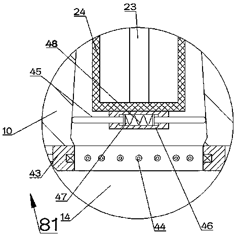
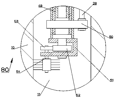
[0019] Reference Figure 1-6 , According to an embodiment of the present invention, a combustion boiler flue gas treatment equipment for a thermal power plant includes a device box 10 in which an air inlet pipe 11 is provided. A cleaning mechanism 80 capable of cleaning the inner wall of the air inlet duct 11 and sucking smoke is provided. The cleaning mechanism 80 includes a spline shaft 32 rotatably arranged on the top wall of the air inlet duct 11. A spline sleeve 49 is spli...


PUM


Abstract

The invention discloses combustion boiler flue gas treatment equipment for a thermal power plant. The equipment comprises a device box body, wherein an air inlet pipeline is arranged in the device boxbody. According to the invention, when a first motor is started, the first motor drives fan blades to rotate, and the fan blades rotate to suck flue gas generated in a power generation boiler into the air inlet pipeline so as to suck the flue out of the burning boiler, so that the flue gas cannot flow backward, and can be subjected to medicated bath and waste heat recovery treatment, the finallydischarged flue gas can meet the requirement of environmental protection, good resource utilization efficiency can be achieved, carbon deposited on the inner wall of the pipeline can be cleaned, and the service life of the equipment is ensured.

Description

Technical field [0001] The invention relates to the field of power generation, in particular to a combustion boiler flue gas treatment equipment used in a thermal power plant. Background technique [0002] When a thermal power plant generates electricity, it needs to burn a large amount of coal, and when coal is burned, a large amount of flue gas will be generated. These flue gas will affect the environment when discharged at will. At present, some equipment for processing flue gas only It is only the prevention and treatment of the flue gas so that the flue gas will not pollute the environment, but the flue gas also contains a lot of heat, and the emission will cause a lot of waste of resources. Moreover, when some flue gas is processed, the flue gas will not follow The circulation of the pipeline may cause backflow, which is not conducive to the combustion of the fuel in the boiler. After a long period of use, there will be a large amount of carbon deposits on the inner wall of...

Claims


Application Information

Patent Timeline
Patent Type & Authority Applications(China)
IPC IPC(8): B01D53/78B01D50/00
CPCB01D53/78B01D2258/0283B01D50/60
Inventor 不公告发明人
Owner TAIZHOU LUQIAO BOREN ENVIRONMENTAL PROTECTION EQUIP CO LTD
Learn More