Aviation airborne knife-shaped antenna

An aircraft and blade-shaped technology, which is applied to antennas, folding antennas, and antenna components, can solve the problems of inconvenient parts maintenance and replacement, and the overall radiation area of ​​the antenna is fixed, so as to achieve excellent use effects and increase effective radiation area, the effect of increasing gain performance

Inactive Publication Date: 2020-04-28
单炜
View PDF9 Cites 0 Cited by
  • Summary
  • Abstract
  • Description
  • Claims
  • Application Information

AI Technical Summary

Problems solved by technology

[0005] The purpose of the present invention is to provide an airborne knife antenna to solve the problem that the overall radiation area of ​​the antenna proposed in the above background technology is mostly fixed, and the expansion gain cannot be adjusted according to the complex battlefield environment, so as to improve the signal reception of the antenna. In addition, most of the antenna shells are designed as a closed one-piece structure, which is not easy to disassemble for maintenance and replacement of parts

Method used


Image

  • Aviation airborne knife-shaped antenna
  • Aviation airborne knife-shaped antenna
  • Aviation airborne knife-shaped antenna

Examples


Embodiment Construction

[0029] The following will clearly and completely describe the technical solutions in the embodiments of the present invention with reference to the accompanying drawings in the embodiments of the present invention. Obviously, the described embodiments are only some, not all, embodiments of the present invention.

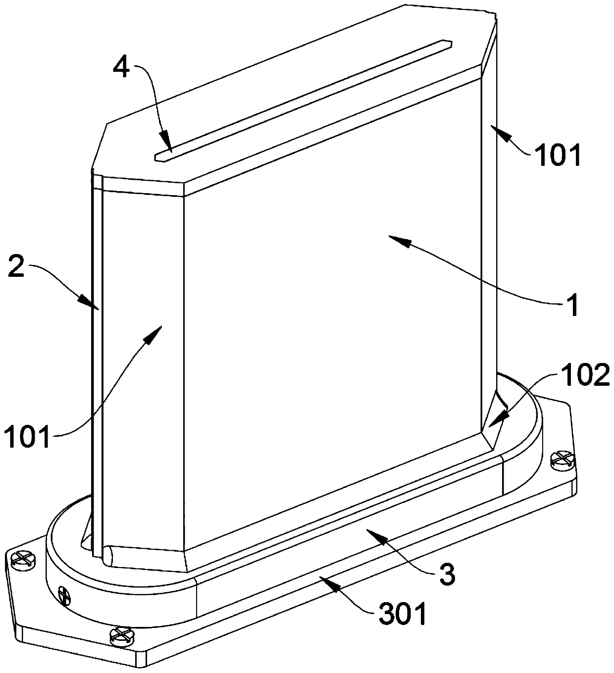
[0030] see Figure 1 to Figure 10 , an embodiment provided by the present invention: an airborne knife antenna, including a shell antenna plate 1, the shell antenna plate 1 includes a wind deflector 101, a fence 102 and a positioning wedge 103, two shell antennas The front and rear ends of the board 1 are symmetrically supported by two air deflectors 101, and the two shell antenna plates 1 are left and right symmetrically supported together to form the main shell; slot, and the two expansion antenna boards 2 are slidably installed in these two slots, the expansion antenna board 2 includes a connecting rod 201, and the two expansion antenna boards 2 are all rotated on...


PUM


Abstract

The invention discloses an aviation airborne knife-shaped antenna, relates to the technical field of aviation airborne antennas, and solves the problems that most of existing conductor antennas and outer antenna shells are of closed integrated structure design, and parts are inconvenient to disassemble for maintenance and replacement. The aviation airborne knife-shaped antenna comprises shell antenna plates, each shell antenna plate comprises air deflectors, a blocking and leaning surrounding strip and a positioning wedge block, the front ends and the rear ends of the two shell antenna platessymmetrically and obliquely support the two air deflectors, and the two shell antenna plates are bilaterally symmetrical and jointly support to form a shell of a main body; a threaded locking rod is hoisted in the middle of a groove in the bottom of a mounting seat in a cross-brace manner; a through groove is formed in the top end supporting and connecting plate of the shell antenna plate, and thetop end section of the lifting antenna plate is inserted into the through groove in an abutting mode. The two rows of squeezing and pushing plates can be limited and slide between the squeezing and pushing plates and the top plate of the mounting base through the two limiting barrier strips, and the squeezing and pushing plates are prevented from rotating along with screwing and shaking of the threaded locking rod.

Description

technical field [0001] The invention relates to the technical field of aviation airborne antenna structures, in particular to an aviation airborne knife antenna. Background technique [0002] The aviation airborne knife antenna is the component that radiates and receives electromagnetic waves in the military tactical security communication system. The received electromagnetic waves are transformed into high-frequency oscillating signals and transmitted to the receiver. The efficiency index is the ratio of the antenna radiation power to the input power. Due to its good aerodynamic performance, it has been widely used in wireless systems such as broadband monitoring and communication of aircraft. [0003] For example, the patent No. CN201710303265.2 discloses an airborne ultrashort-wave broadband knife antenna, which includes a dielectric board, a metal flange and a coaxial RF connector, wherein the dielectric board is printed with radiation patches, long branches, Short bra...

Claims


Application Information

Patent Timeline
IPC IPC(8): H01Q1/08H01Q1/12H01Q1/28H01Q1/38H01Q1/42H01Q1/50
CPCH01Q1/08H01Q1/1207H01Q1/28H01Q1/38H01Q1/42H01Q1/50
Inventor 单炜
Owner 单炜
Why Eureka
Try Eureka