
Power battery cover plate and manufacturing method thereof

A technology of power battery and manufacturing method, which is applied to battery pack components, battery box/jacket, small-sized battery/battery pack, etc. Efficiency, improving the manufacturing yield, and simplifying the manufacturing process

Active Publication Date: 2020-04-28
SHENZHEN KEDALI IND CO LTD
View PDF8 Cites 6 Cited by
  • Summary
  • Abstract
  • Description
  • Claims
  • Application Information

AI Technical Summary

Problems solved by technology

[0002] At present, most of the structure of the power battery cover plate needs to be fixed by the laser welding process. During the welding manufacturing process, laser welding is prone to connection defects, and the manufacturing cost is high. In order to facilitate welding, some additional structures are required for laser welding. Therefore, the pole will occupy a large internal space of the battery

Method used


Image

  • Power battery cover plate and manufacturing method thereof
  • Power battery cover plate and manufacturing method thereof
  • Power battery cover plate and manufacturing method thereof

Examples


Embodiment 1

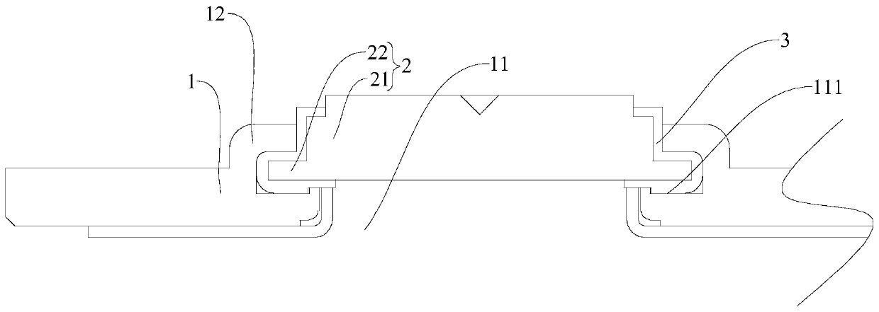
[0047] Refer below Figure 1-Figure 4A power battery cover plate according to a specific embodiment of the present invention is described.

[0048] Such as Figure 1-Figure 4 As shown, the power battery cover plate of this embodiment includes a top cover 1, a pole 2 and a first rubber covering part 3, and a countersunk hole 11 is provided on the top cover 1, and the countersunk hole 11 has a first stepped surface 111. The cover 1 is provided with a flange 12 arranged around the countersunk hole 11. The pole 2 includes a body 21 and a protruding ring 22 connected to the body 21. The protruding ring 22 is connected to the lower end surface of the body 21, and the lower end surface of the protruding ring 22 stop on the first stepped surface 111 . The flange 12 is crimped on the protruding ring 22 after being completed, and the first rubber covering part 3 covers the surface of the main body 21 and the protruding ring 22 .

Embodiment 2

[0050] Such as Figure 5 As shown, the power battery cover plate of this embodiment is similar in structure to the power battery cover plate of the above-mentioned embodiment, the difference is that the cover plate of this embodiment also includes a second rubber covering member covering the flange 12 4.

Embodiment 3

[0052] Such as Figure 6 As shown, the power battery cover plate of this embodiment is similar in structure to the power battery cover plate of the above embodiment, the difference is that the pole 2 of this embodiment is formed as a structure in which the protruding ring 22 surrounds the body 21 . And the body 21 of the pole 2 is disposed through the counterbore 11 , and the lower end surface of the protruding ring 22 abuts against the first stepped surface 111 .

[0053] Refer below Figure 7 The specific steps of the manufacturing method of the power battery cover plate according to the embodiment of the present invention are described.

[0054] The invention also discloses a method for manufacturing the power battery cover, the steps of the method include:

[0055] S1: forming a first rubber covering 3 on the outer peripheral surface of the pole 2;

[0056] S2: placing the pole 2 in the counterbore 11 and making the protruding ring 22 abut against the first stepped surf...


PUM


Abstract

The invention discloses a power battery cover plate and a manufacturing method thereof. The power battery cover plate comprises a top cover, a pole and a first rubber coating piece, wherein the top cover is provided with a counterbore, the counterbore is provided with a first step surface, the top cover is provided with a flange arranged around the counterbore, the pole comprises a body and a convex ring connected with the body, the body is matched in the counterbore, the convex ring is clamped between the first step surface of the counterbore and the flange, and the surfaces of the body and the convex ring are coated with the first rubber coating piece. According to the power battery cover plate, due to the fact that the top cover is provided with the structure capable of being connectedwith the pole convex ring in the pressing mode, limiting connection between the top cover and the pole is achieved, the overall structure of the cover plate is simplified, the internal space of a power battery is increased, and assembly of the cover plate is facilitated.

Description

technical field [0001] The invention relates to the technical field of power batteries, in particular to a power battery cover plate and a manufacturing method thereof. Background technique [0002] At present, most of the structure of the power battery cover plate needs to be fixed by the laser welding process. During the welding manufacturing process, laser welding is prone to connection defects, and the manufacturing cost is high. In order to facilitate welding, it is necessary to set up some additional structures for laser welding. Therefore, the pole will occupy a large internal space of the battery. Contents of the invention [0003] The first object of the present invention is to provide a cover plate for a power battery, which has a relatively simple structure, is convenient to manufacture, and has a high manufacturing yield. [0004] The second object of the present invention is to provide a method for manufacturing a power battery cover, and the manufacturing co...

Claims


Application Information

Patent Timeline
Patent Type & Authority Applications(China)
IPC IPC(8): H01M2/04H01M2/30
CPCH01M50/148H01M50/543Y02E60/10H01M50/15H01M50/184H01M50/188H01M50/193
Inventor 励建炬邱宜升石从兵
Owner SHENZHEN KEDALI IND CO LTD
Learn More