Portable nuclear instrument system signal detection and fault positioning device

A system signal and fault location technology, applied in the detection field, can solve problems such as difficult to find and locate faults, consume manpower and material resources, and inconvenience, and achieve the effects of troubleshooting and positioning, good electromagnetic compatibility, and guaranteed signal accuracy

Inactive Publication Date: 2020-04-28
中广核工程有限公司 +2
View PDF10 Cites 5 Cited by
  • Summary
  • Abstract
  • Description
  • Claims
  • Application Information

AI Technical Summary

Problems solved by technology

In the past investigations of the source range abnormal count rate flashing problem of the nuclear instrument system, in order to determine the faulty section, the signal cable needs to be untied section by section, but the source range signal and the high voltage are the same cable, and the cables cannot be untied. Signals observed on the cabinet
And the fault phenomenon is flashing, it may take a long time of continuous monitoring to catch the fault
Moreover, due to the lack of suitable fault location tools, it is difficult to find and locate the root cause of the fault on site. A lot of manpower and material resources are spent in the actual fault handling process. In the end, the most probable cause can only be obtained through the analysis of the fault phenomenon.
[0003] Individual suppliers of nuclear instrumentation systems in domestic nuclear power plants provide simple test devices that can be used to collect source-range pulse signals, but the functions are relatively simple, and the current measurement functions of intermediate range and power range cannot be realized, and the measurement data cannot be stored for a long time. and use effects are very limited, inconvenient for the field

Method used


Image

  • Portable nuclear instrument system signal detection and fault positioning device
  • Portable nuclear instrument system signal detection and fault positioning device
  • Portable nuclear instrument system signal detection and fault positioning device

Examples


Embodiment Construction

[0044]In order to make the purpose, technical solutions and advantages of the embodiments of the present invention clearer, the technical solutions in the embodiments of the present invention will be clearly and completely described below in conjunction with the accompanying drawings in the embodiments of the present invention. Obviously, the described embodiments It is some embodiments of the present invention, but not all of them. Based on the implementation manners in the present invention, all other implementation manners obtained by persons of ordinary skill in the art without creative efforts fall within the protection scope of the present invention. Accordingly, the following detailed description of the embodiments of the invention provided in the accompanying drawings is not intended to limit the scope of the claimed invention, but merely represents selected embodiments of the invention. Based on the implementation manners in the present invention, all other implementa...


PUM


Abstract

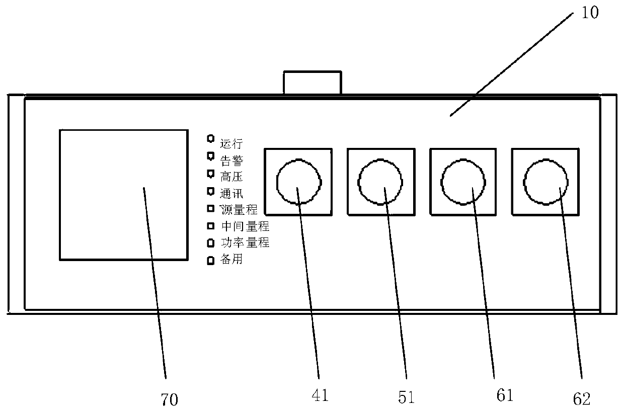
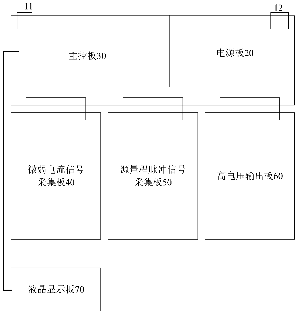
The invention provides a portable nuclear instrument system signal detection and fault positioning device. The device comprises a shell, a power supply board, a main control board, a weak current signal acquisition board, a source range pulse signal acquisition board, a high voltage output board and a liquid crystal display board, wherein an accommodating cavity is formed in the shell; the power supply board, the main control board, the weak current signal acquisition board, the source range pulse signal acquisition board and the high voltage output board are all placed in the accommodating cavity; the liquid crystal display panel is fixed on the surface of the shell, and the power panel, the weak current signal acquisition board, the source range pulse signal acquisition board, the high voltage output board and the liquid crystal display panel are all electrically connected with the main control board; the weak current signal acquisition board, the source range pulse signal acquisition board and the high voltage output board are provided with corresponding HN terminals; and the HN terminal is arranged on the surface of the shell. According to the invention, when an abnormal signaloccurs, a fault section can be troubleshot through a segmentation test function of the device, so that troubleshooting and positioning are realized.

Description

technical field [0001] The invention relates to the detection field, in particular to a portable nuclear instrument system signal detection and fault location device. Background technique [0002] Nuclear power plants use nuclear instrumentation systems for online power monitoring. The signals of nuclear instrumentation systems are weak, and are easily affected by the quality of the measurement circuit installation or external interference. In the actual project construction process, the source range neutron count rate flash anomalies of the nuclear instrumentation system have occurred many times. In the past investigations of the cause of the abnormal count rate flashing problem of the source range of the nuclear instrument system, in order to determine the faulty section, the signal cable needs to be untied section by section, but the source range signal and the high voltage are the same cable, and the cable cannot be disconnected. A signal was observed on the cabinet. M...

Claims


Application Information

Patent Timeline
Patent Type & Authority Applications(China)
IPC IPC(8): G01R35/00G01R19/25G01R15/09
CPCG01R35/00G01R19/2513G01R15/09
Inventor 李兴强
Owner 中广核工程有限公司
Why Eureka
Try Eureka