
A municipal drainage ditch with a planted layer of vegetation

A drainage ditch, municipal technology, applied in the direction of removing sewage, drainage structures, water supply devices, etc., can solve the problems of reduced water flow through the filter, reduced filtration effect, and water in the road area, so as to facilitate discharge, reduce blockage, improve The effect of greening the environment

Active Publication Date: 2020-12-18
卢佳毅
View PDF1 Cites 0 Cited by
  • Summary
  • Abstract
  • Description
  • Claims
  • Application Information

AI Technical Summary

Problems solved by technology

[0004] Although the mud and debris are filtered through the soil layer and the filter to prevent clogging; however, after a period of use, the filtered mud and debris will accumulate on the surface of the filter and cover the filter, and its filtering effect will be reduced. , the water flow of the filter is also reduced, especially when the drainage increases, it cannot match the drainage demand, resulting in poor drainage and even water accumulation on the road

Method used


Image

  • A municipal drainage ditch with a planted layer of vegetation
  • A municipal drainage ditch with a planted layer of vegetation
  • A municipal drainage ditch with a planted layer of vegetation

Examples


Embodiment Construction

[0036]The present invention will be described in further detail below in conjunction with the accompanying drawings.

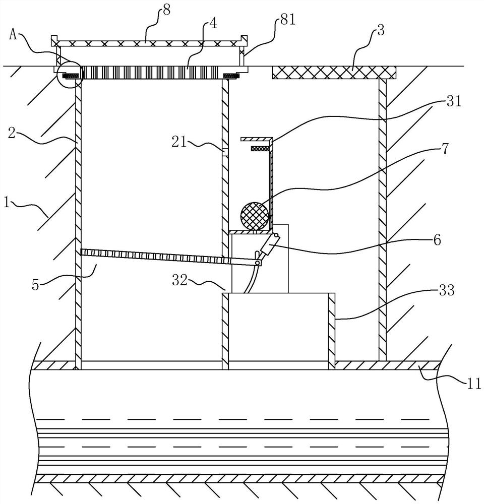
[0037] refer to figure 1 , is a municipal drainage ditch with a vegetation planting layer disclosed by the present invention, including a base layer 1, a municipal drainage pipe 11 arranged under the base layer 1, a drainage pipe installed in the base layer 1 and respectively connected to the municipal drainage pipe 11 The well 2 and the inspection well 3, and the mesh grid 4 covered on the port of the drainage well 2.

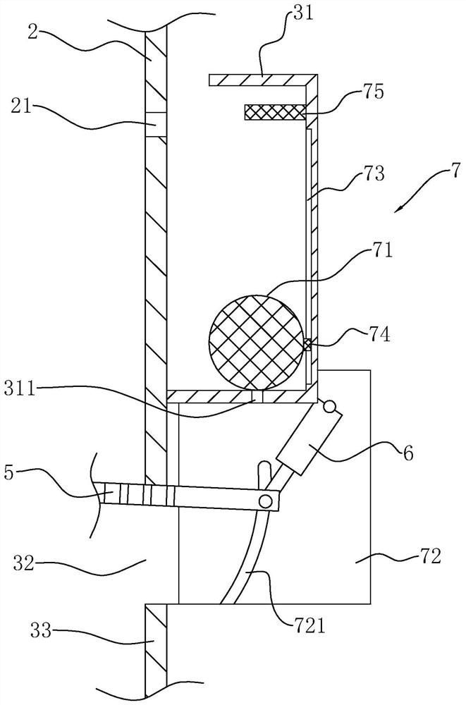
[0038] refer to figure 1 , figure 2 As shown, wherein, a filter screen 5 is installed in the drainage well 2, and one end of the filter screen 5 is hinged on the inner side wall of the drainage well 2, and an overflow hole 21 is provided on the drainage well 2 above the filter screen 5. 2 A reservoir 31 is installed in the inspection well 3 outside, and the reservoir 31 is located below the overflow hole 21; a discharge port 32 is opened o...


PUM


Abstract

The invention relates to a municipal drainage ditch with a vegetation planting layer and relates to the technical field of municipal drainage. The municipal drainage ditch comprises a base layer, a municipal drainage pipe, a drainage well, a grid and a filtering net. One end of the filtering net is hinged to the inner side wall of the drainage well; an overflow hole is formed in the drainage well;an impounding reservoir is installed outside the drainage well; the impounding reservoir is located below the overflow hole; an effusion opening is formed in the drainage well; the other end of the filtering net abuts against the upper portion of the effusion opening and extends to the outside of the effusion opening; a driving cylinder is disposed in the base layer; a switch starting device is installed in the impounding reservoir and electrically connected with the driving cylinder; a filtered residue filtering cavity is formed in the base layer and located in the position, at the outer endof the drainage well, below the effusion opening; when the filtering net is opened, one end of the filtering net abuts against a port of the filtered residue filtering cavity; and the filtered residue filtering cavity is located above the municipal drainage pipe and communicates with the municipal drainage pipe. The municipal drainage ditch with the vegetation planting layer has the effects thatthe drainage property of the municipal drainage ditch is improved, and the phenomenon of blocking of an existing drainage ditch is reduced.

Description

technical field [0001] The invention relates to the technical field of municipal drainage, in particular to a municipal drainage ditch with a vegetation planting layer. Background technique [0002] Drainage ditch is an indispensable channel in municipal construction. While effectively discharging urban sewage, it can also play a role in mitigating during heavy rain seasons. However, urban sewage and rainwater mixed with sediment will also be discharged into the drainage In the ditch, it will cause blockage of the drainage ditch, resulting in poor drainage and water accumulation on the road. [0003] The existing Chinese patent that can be referred to as CN206015842U discloses a municipal drainage ditch with a vegetation planting layer, including a base and a side wall above the base, the side wall is formed by pouring concrete, and the inner side of the side wall is set There is a reinforcement layer, a buffer ditch is provided at the root of the reinforcement layer, a fil...

Claims


Application Information

Patent Timeline
Patent Type & Authority Patents(China)
IPC IPC(8): E03F1/00E03F3/04E03F5/04E03F5/06E03F5/14E03F7/00
CPCE03F1/00E03F3/04E03F5/0401E03F5/0404E03F5/06E03F7/00E03F2005/065
Inventor 卢佳毅
Owner 卢佳毅
Learn More