Ship lift tower structure provided with thin pile raft foundation and layered strongly-constrained box girders

A technology of raft foundation and ship lift, which is applied in basic structure engineering, construction, etc., can solve the problems of unfavorable secondary stress of navigable aqueduct structure, affecting the safe operation of water stop, large plane torsion effect, etc., and achieves the control of uneven settlement , the effect of increasing lateral stiffness and reducing secondary stress

Pending Publication Date: 2020-04-28
CHANGJIANG SURVEY PLANNING DESIGN & RES
View PDF0 Cites 2 Cited by
  • Summary
  • Abstract
  • Description
  • Claims
  • Application Information

AI Technical Summary

Problems solved by technology

[0004] In addition, if the upstream and downstream of the vertical ship lift are connected to a large-scale navigable aqueduct, due to the large difference in rigidity of the two structures, the coordination problem of lateral deformation is prominent, which may affect the safe operation of the water stop, and the structure of the navigable aqueduct may also produce unfavorable secondary stress
[0005] Moreover, there is a large difference in the stiffness of the tower structure of the ship lift itself in the flow direction and the cross flow direction, and the plane torsion effect is relatively large

Method used


Image

  • Ship lift tower structure provided with thin pile raft foundation and layered strongly-constrained box girders
  • Ship lift tower structure provided with thin pile raft foundation and layered strongly-constrained box girders
  • Ship lift tower structure provided with thin pile raft foundation and layered strongly-constrained box girders

Examples


Embodiment Construction

[0032] The present invention will be further described in detail below in conjunction with the accompanying drawings and specific embodiments.

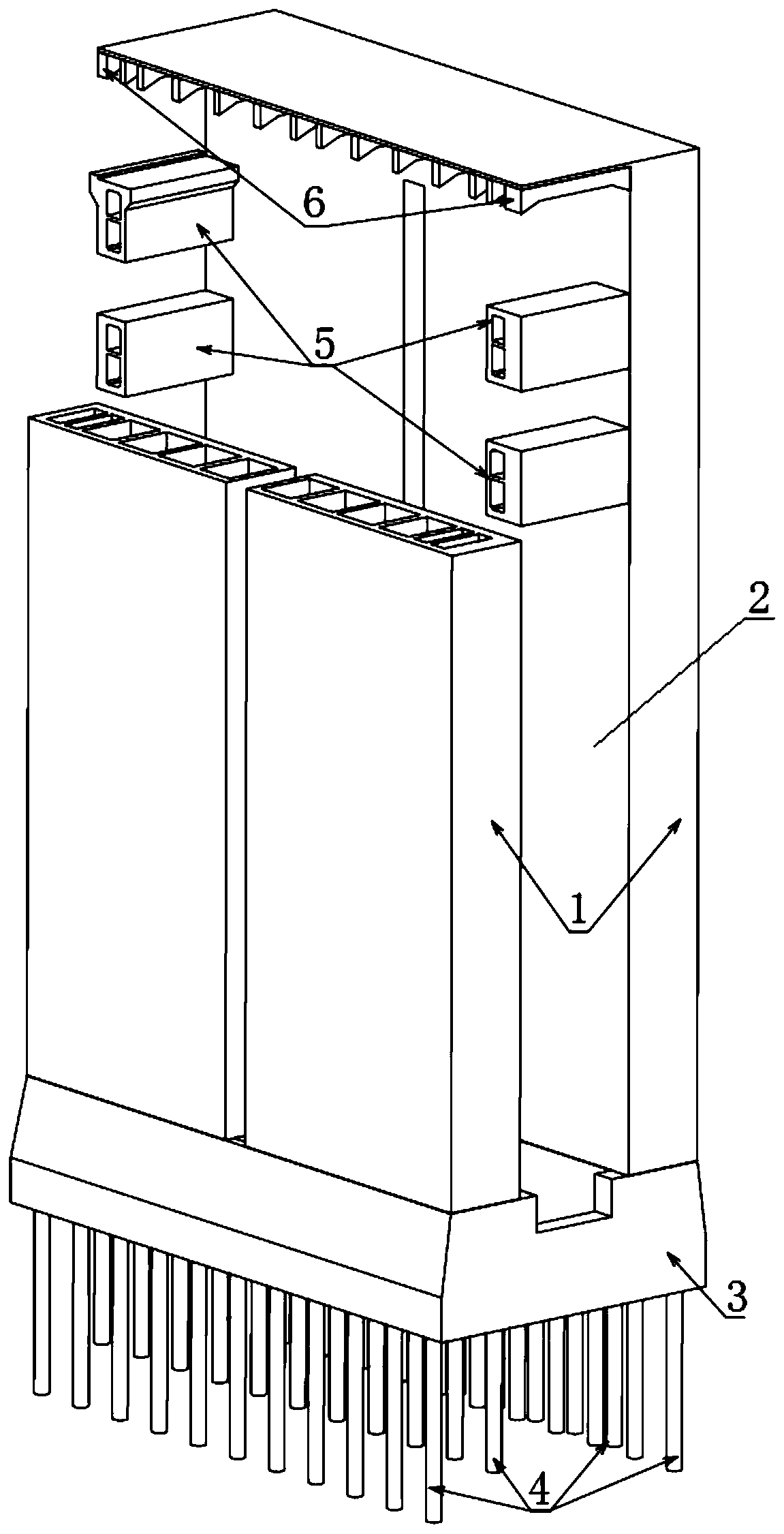
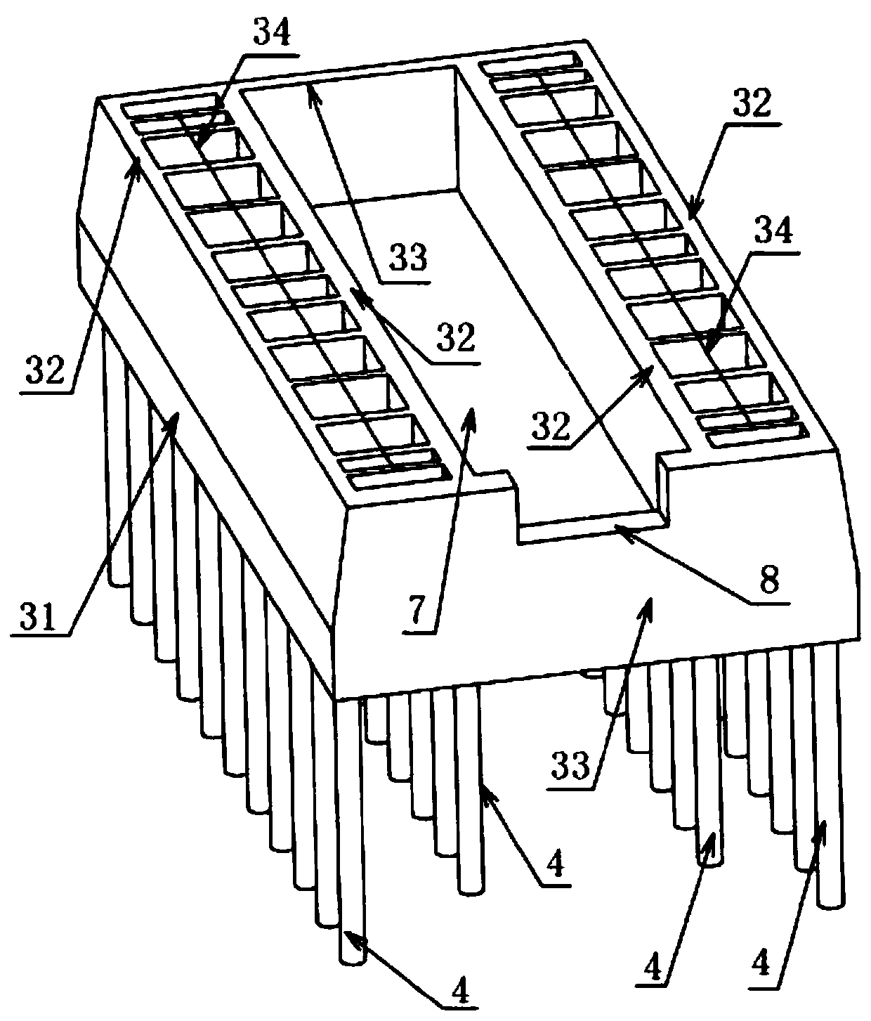
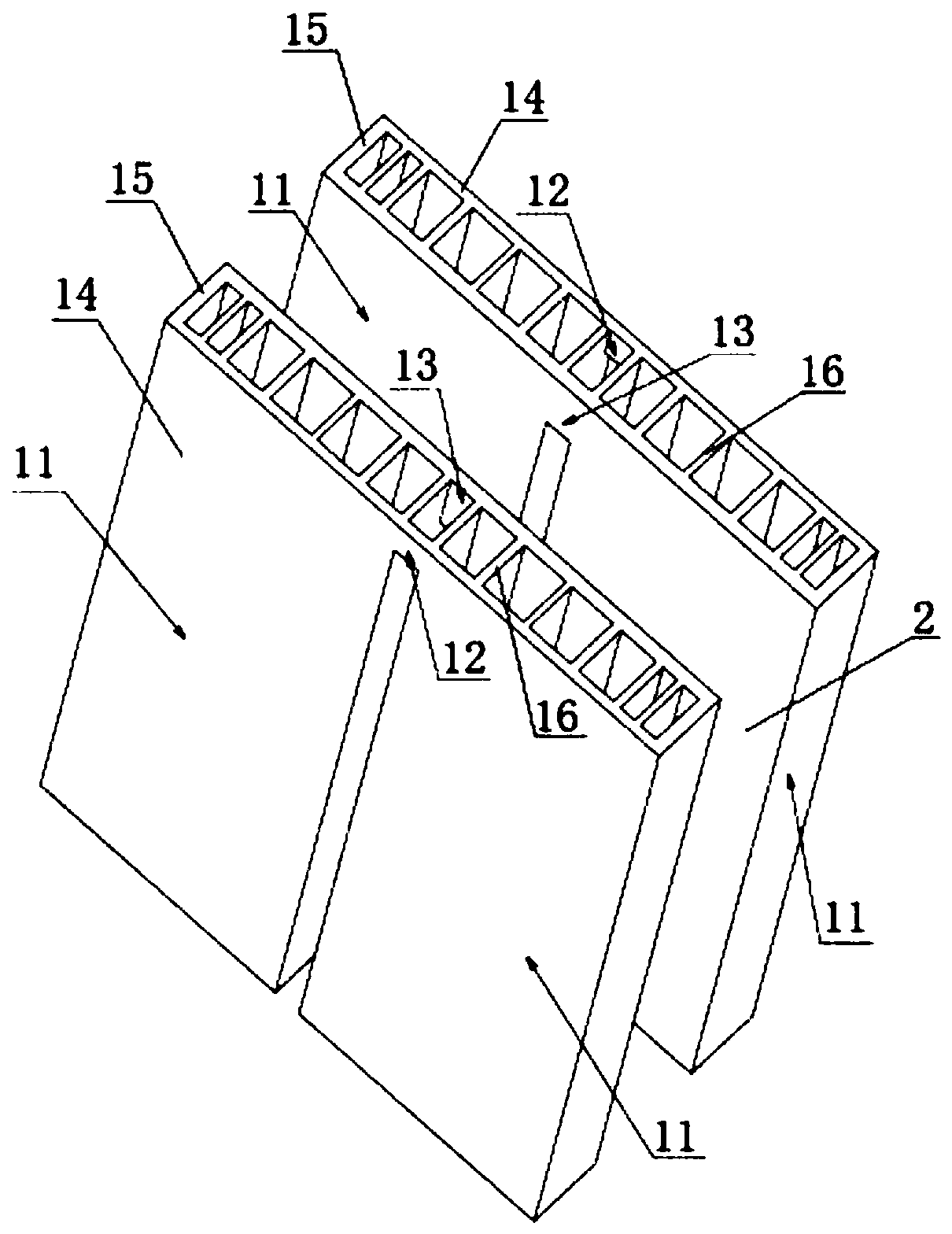
[0033] like figure 1 As shown, the ship lift tower structure of the present invention is provided with sparse pile raft foundation and layered strong restraint box girder, including the tower main body, and the tower main body includes two left and right symmetrical tower groups 1, two tower groups The space between 1 forms a ship compartment 2, and a raft foundation 3 is arranged directly under the main body of the tower column, and a pile group including several piles 4 is arranged directly under the foundation 3, and the piles 4 are inserted into the foundation of the ship lift In the upper part of the two tower column groups 1, there are several layers of connecting box girder groups. The two ends of 5 are fixedly connected to the two tower column groups 1 respectively, and a top beam group including several top beams 6 is arranged...


PUM


Abstract

The invention relates to the technical field of water conservancy projects and navigation projects, and discloses a ship lift tower structure provided with a thin pile raft foundation and layered strongly-constrained box girders. The ship lift tower structure comprises a tower main body; the tower main body comprises two bilaterally-symmetric tower groups; the space between the two tower groups form a ship compartment; the raft foundation is arranged under the tower main body; a thin pile group if arranged under the raft foundation; multiple layers of linkage box girder groups are arranged between the upper middle parts of the two tower groups; each layer of the linkage box girder group comprises two linkage box girders located in the most upstream and downstream positions respectively; atop girder group comprising a plurality of top girders is arranged between the tops of the two tower groups; and the two ends of each top girder are in fixed-end connection with the two tower groups respectively. According to the ship lift tower structure provided with the thin pile raft foundation and the layered strongly-constrained box girders, differential settlement and later flowing deformation of a ship lift foundation are controlled effectively, transverse deformation of the structure is reduced, torsional deformation of the towers is avoided, and the stress on each key part of a shiplift structure is reduced.

Description

technical field [0001] The invention relates to the fields of water conservancy engineering and water transportation engineering, in particular to a ship lift tower column structure provided with pile sparse raft foundations and layered strong restraint box girders. Background technique [0002] Navigable structures such as ship locks and ship lifts are the infrastructure for overcoming water head differences in water conservancy, hydropower and water transportation hub projects and ensuring the normal navigation of cascade development rivers. For high-head navigable facilities, vertical ship lifts are more and more widely used as the main navigable building type, such as the ship lifts of the Three Gorges, Geheyan, Gaobazhou, Tingzikou, Xiangjiaba and other pivotal projects. [0003] With the rapid development of the national economy, there is an increasing demand for the construction of navigation facilities in the mountains and valleys in the southwest of my country, and ...

Claims


Application Information

Patent Timeline
Patent Type & Authority Applications(China)
IPC IPC(8): E02D27/44
CPCE02D27/44
Inventor 宋志忠吴俊东汪亚超陈小虎王程林新志邓润兴周浩
Owner CHANGJIANG SURVEY PLANNING DESIGN & RES
Why Eureka
Try Eureka