Die pressing and transferring mechanism for spherical lens

A spherical lens and conveying mechanism technology, applied in the field of molding, can solve the problems of reducing product quality, increasing product loss, lack of cleaning measures, etc., to achieve the effect of improving product quality and reducing product loss

Inactive Publication Date: 2020-04-28
永豪光电(中国)有限公司
View PDF13 Cites 0 Cited by
  • Summary
  • Abstract
  • Description
  • Claims
  • Application Information

AI Technical Summary

Problems solved by technology

[0004] However, there are some problems in the use of the existing spherical lens molding equipment. 1. Most of the spherical lens molding equipment currently on the market has only one molding device, and the process of adding materials is relatively inconvenient, thereby reducing its production efficiency. Increased labor costs. 2. At present, there is a lack of good cleaning measures for spherical lens molding equipment on the market, so that debris interference is prone to occur during molding, thereby reducing product quality. 3. Currently, the spherical lens is currently on the market. There is a lack of a rapid heat dissipation function during molding, so the temperature is high during molding, and it is easy to cause molding failure, which increases the loss of its products

Method used


Image

  • Die pressing and transferring mechanism for spherical lens
  • Die pressing and transferring mechanism for spherical lens
  • Die pressing and transferring mechanism for spherical lens

Examples


Embodiment Construction

[0021] In order to make the purpose, technical solutions and advantages of the present invention clearer, the present invention will be further described in detail below in conjunction with the accompanying drawings. Obviously, the described embodiments are only some of the embodiments of the present invention, rather than all of them. Based on the embodiments of the present invention, all other embodiments obtained by persons of ordinary skill in the art without making creative efforts belong to the protection scope of the present invention.

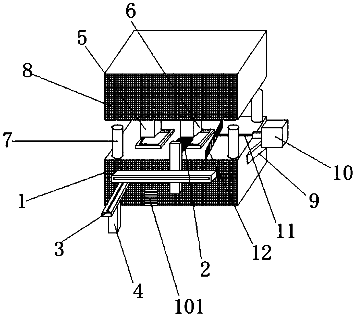
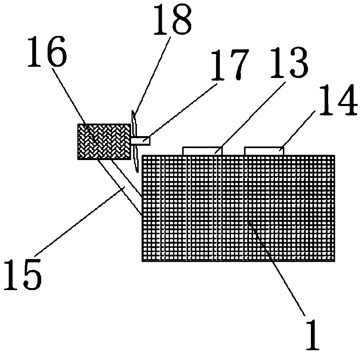
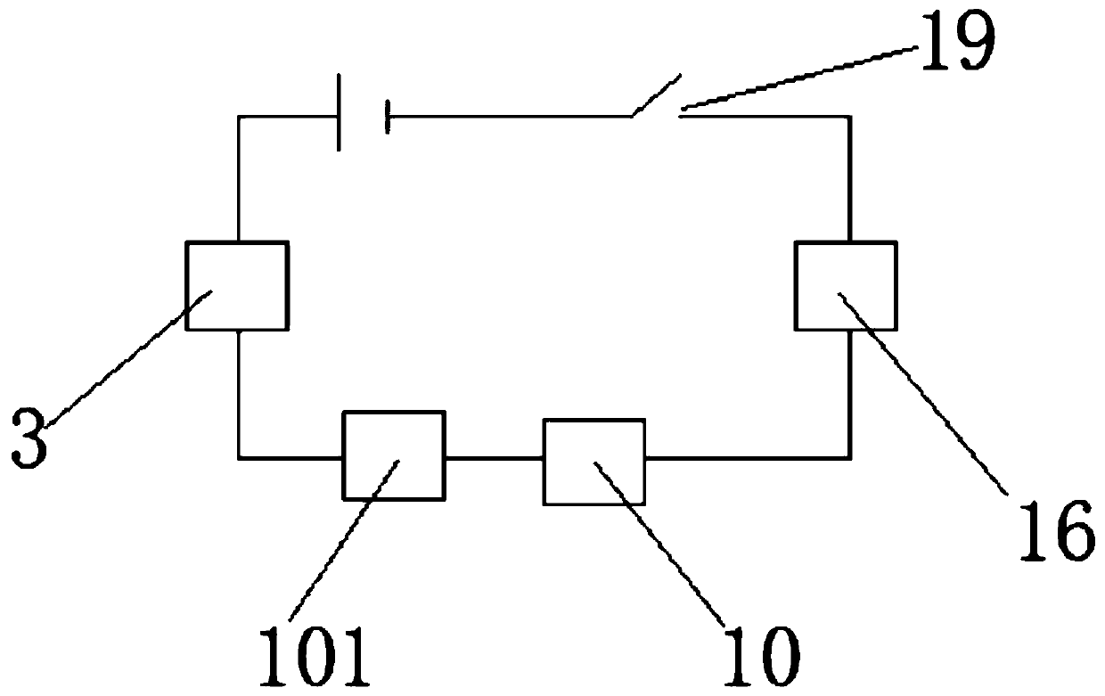
[0022] The following will combine Figure 1~Figure 3 The molding and transfer mechanism for a spherical lens according to an embodiment of the present invention will be described in detail.

[0023] refer to figure 1 , figure 2 and image 3 As shown, the spherical lens molding and transmission mechanism provided by the embodiment of the present invention includes a lower mold 1, the surface of the lower mold 1 is movably connected w...


PUM


Abstract

The invention discloses a die pressing and transferring mechanism for a spherical lens and belongs to the field of die pressing. The die pressing and transferring mechanism comprises a lower die, wherein a clamp is movably connected with the surface of the lower die; one end of the clamp is detachably connected onto the surface of a triaxial manipulator; the bottom of the triaxial manipulator is detachably connected with a vertical rod; the surface of the lower die is fixedly connected with a die cavity A and a die cavity B; a holddown A and a holddown B are fixedly connected with the bottom of an upper die, that is, the die cavity A and the die cavity B fixedly connected with the surface of the lower die are connected with the holddown A and the holddown B fixedly connected with the bottom of the upper die in a matching manner, so that formation of two dies can be simultaneously carried during die pressing to increase the yield; the triaxial manipulator works to drive the clamp fixedly connected with one end of the triaxial manipulator to work, so that fast changing and taking are realized; and the vertical rod detachably connected with the bottom of the triaxial manipulator is adopted to fix the dies, so that the yield is doubled, the labor intensity is lowered, and the productivity is improved.

Description

technical field [0001] The invention relates to the field of molding, in particular to a molding and transmission mechanism for spherical lenses. Background technique [0002] Molding is the abbreviation of compression molding, also known as compression molding. Plastic or rubber compound is molded into products by means of heating and pressure in a closed mold cavity. Plastic processing is also a rubber processing method. Generally, powder, granular, pellet, sheet, or even a material similar to the product is made first. The blank is placed in the cavity of the heated mold, and then the mold is closed and pressed to make it shaped and cured or vulcanized, and then the product is demoulded. This method is especially suitable for the molding process of thermosetting plastics. See thermosetting resins. The disadvantage is that the production cycle is long, the efficiency is low, and the dimensional accuracy of the product is poor. [0003] Patent No. 201910384459.9 The prese...

Claims


Application Information

Patent Timeline
Patent Type & Authority Applications(China)
IPC IPC(8): B29C43/02B29C43/36B29C43/32B29C43/52B29C33/72B29L11/00
CPCB29C33/72B29C43/02B29C43/32B29C43/36B29C43/52B29L2011/0016
Inventor 姚祖义李耀春金小伟
Owner 永豪光电(中国)有限公司
Why Eureka
Try Eureka