Anchor frame type stirring paddle for flask
A technology of anchor frame and stirring paddles, which is applied in the field of anchor frame stirring paddles for flasks, can solve the problems of low accuracy of experimental data, poor stirring effect, and great influence on experimental results, etc., to achieve increased contact area, stable connection, Enhance the effect of suction force
- Summary
- Abstract
- Description
- Claims
- Application Information
AI Technical Summary
Problems solved by technology
Method used
Image
Examples
Embodiment 1
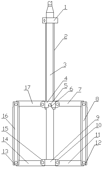
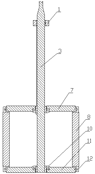
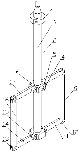
[0020] Such as figure 1 , figure 2 , image 3 The shown flask uses an anchor frame type stirring paddle, which is provided with a transmission shaft 3, an upper paddle hub 4 and a lower paddle hub 9 are arranged on the transmission shaft 3, and the left and right sides of the upper paddle hub 4 are respectively hinged with rectangular strip-shaped upper left Paddle 17 and upper right paddle 7, lower paddle hub 9 left and right sides are respectively hinged with the left lower paddle 14 and the right lower paddle 11 of rectangular elongated shape, the left end of left upper paddle 17 and left lower paddle 14 is respectively connected with The upper end and the lower end of the left rocker arm 16 are hinged, and the right end of the upper right paddle 7 and the lower right paddle 11 are hinged with the upper end and the lower end of the right rocker 8 respectively; The hinges of the left and right sides of the lower paddle hub 9 and the hinges of the left lower blade 14 and t...
Embodiment 2
[0025] Such as Figure 4 , Figure 5 , Figure 6 The shown flask uses an anchor frame type stirring paddle, and the difference with embodiment 1 is that the upper paddle hub 4 is fixedly connected with the transmission shaft 3; The lower end of shaft 3 can be inserted into the drive shaft slot. The drive shaft and the lower propeller hub are made of soft magnetic materials. The upper part of the drive shaft is provided with a magnet mounting part for placing magnets. The magnet mounting part is provided with a magnet that can be installed and removed 18. The magnet installation part can be a suction notch provided on the upper part of the transmission shaft. The magnet 18 can be embedded in the suction notch to attract and magnetize the transmission shaft. The magnet installation part can also be an annular shape on the upper part of the transmission shaft. The provided snap-in notch can also be without any notch, and the magnet 18 is arc-shaped and directly attracts the slo...
Embodiment 3
[0028] Such as Figure 7 , Figure 8 , Figure 9 The shown flask uses an anchor frame type stirring paddle. The difference from Example 1 is that the upper paddle hub 4 and the transmission shaft 3 are axially fixed, and the circumferential direction can be rotatably connected within a limited angle. The upper paddle hub 4 and the transmission shaft 3 circle It can be rotated and connected within an angle of 5-90°, preferably within an angle of 10-30°; the lower propeller hub 26 is in the shape of a connecting sleeve, and the lower end of the drive shaft can be inserted into the lower propeller hub, and the front side of the lower propeller hub 26 The wall is provided with an open L-shaped connection control notch 25, and the front side of the lower end of the transmission shaft 3 is provided with a cylindrical control protrusion 24 that cooperates with the L-shaped connection control notch 25. The control protrusion 24 is located at the lower end of the transmission shaft. ...
PUM
 Abstract
Description
Claims
Application Information
 - Generate Ideas
- Intellectual Property
- Life Sciences
- Materials
- Tech Scout
- Unparalleled Data Quality
- Higher Quality Content
- 60% Fewer Hallucinations
Browse by: Latest US Patents, China's latest patents, Technical Efficacy Thesaurus, Application Domain, Technology Topic, Popular Technical Reports.
© 2025 PatSnap. All rights reserved.Legal|Privacy policy|Modern Slavery Act Transparency Statement|Sitemap|About US| Contact US: help@patsnap.com


