Focal length test device

A test device and focal length technology, which is applied in the direction of testing optical performance, lens position determination, optical axis determination, etc., can solve the problem that the collimator objective lens is not suitable for replacement, the collimator objective lens and the reticle are inconvenient to adjust, the replacement of the detector or The reticle process is cumbersome and other problems, to meet the effect of large-range focal length test

Inactive Publication Date: 2020-04-24
CHANGCHUN INST OF OPTICS FINE MECHANICS & PHYSICS CHINESE ACAD OF SCI
View PDF2 Cites 1 Cited by
  • Summary
  • Abstract
  • Description
  • Claims
  • Application Information

AI Technical Summary

Problems solved by technology

In the focal length test device, replacing the light source has no effect on expanding the focal length range, and the process of replacing the detector or reticle is also very cumbersome
The distance between the collimator objective lens and the reticle is inconvenient to adjust during the measurement process, so the collimator objective lens should not be replaced
In this way, only the microscope objective lens is left, but if the microscope objective lens is replaced directly, the distance between the microscope objective lens and the detector needs to be adjusted, which is also very inconvenient

Method used


Image

  • Focal length test device
  • Focal length test device
  • Focal length test device

Examples


Embodiment Construction

[0019] The following will clearly and completely describe the technical solutions in the embodiments of the present invention with reference to the accompanying drawings in the embodiments of the present invention. Obviously, the described embodiments are only some, not all, embodiments of the present invention. Based on the embodiments of the present invention, all other embodiments obtained by persons of ordinary skill in the art without making creative efforts belong to the protection scope of the present invention.

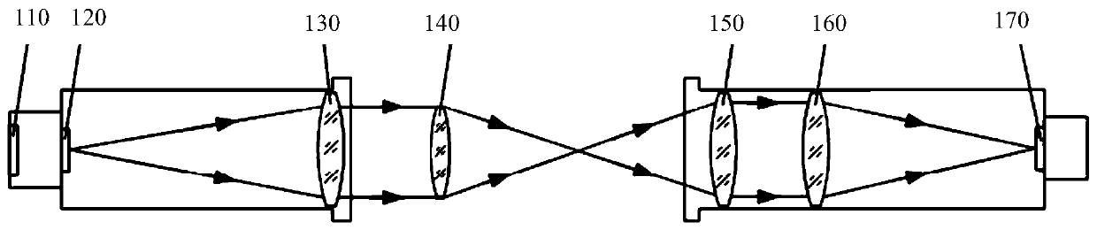
[0020] see figure 1 , is a schematic structural diagram of a focal length testing device provided in an embodiment of the present invention, including: an LED light source 110, a reticle 120, a collimator objective lens 130, an optical lens 140 to be tested, a standard lens 150, a focusing lens 160 and a detector 170, A set of line pairs is engraved on the reticle 120 .

[0021] The working mode of the focal length testing device provided by the foregoing emb...


PUM


Abstract

The invention provides a focal length test device. The light beam emitted by an LED light source illuminates a reticle; a parallel tube objective lens projects the line pair on the reticle into firstparallel light; the first parallel light is incident to the measured optical lens and forms an image of the line pair; the image of the line pair is projected into second parallel light after passingthrough a standard lens; a focus lens receives the second parallel light and focuses the image of the line pair on a detector; the detector receives the image of the line pair and transmits the imageof the line pair to an external computer for processing and calculation so as to obtain the focal length of the measured optical lens. According to the focal length test device, the microscope objective lens is replaced by the standard lens and the focusing lens, and a parallel light path is formed between the two lenses so that the small distance change between the standard lens and the focusinglens has no influence on the test, the standard lens can be conveniently replaced and the requirement of a wide-range focal length test is met.

Description

technical field [0001] The invention relates to the field of optical testing devices, in particular to a focal length testing device. Background technique [0002] Focal length is an important parameter of optical lens. The focal length of the optical lens determines the size of the image and the size of the field of view. In order to grasp the performance of the optical lens and use the optical lens correctly, the focal length of the optical lens must be tested. [0003] The focal length test methods of optical lenses include magnification method and precision angle measurement method. The precision goniometric method requires that the reticle must be precisely focused on the focal plane of the optical lens to be tested. This condition is very inconvenient to realize, so the precision goniometric method is rarely used. Compared with the precision angle measurement method, the magnification method is relatively more convenient to use, so it is used more often. [0004] I...

Claims


Application Information

Patent Timeline
IPC IPC(8): G01M11/02
CPCG01M11/0221
Inventor 袁理马洪涛许洪刚
Owner CHANGCHUN INST OF OPTICS FINE MECHANICS & PHYSICS CHINESE ACAD OF SCI
Why Eureka
Try Eureka