A low-voltage protection method for rail vehicle air-conditioning units
A technology for air-conditioning units and rail vehicles, which is applied in the heating/cooling of railway vehicles, railway car body parts, transportation and packaging, etc. It can solve the problems of frosting and water spraying in the refrigeration system, and achieve the goal of reducing the failure rate and systemic low-voltage protection Effect
- Summary
- Abstract
- Description
- Claims
- Application Information
AI Technical Summary
Problems solved by technology
Method used
Image
Examples
Embodiment 1
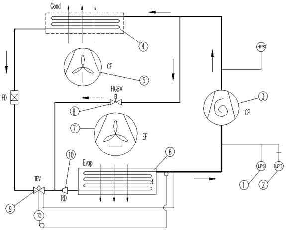
[0025] See attached figure 1 , the present embodiment is based on a rail vehicle air conditioning unit with a low pressure protection switch 1 and a low pressure sensor 2 . The rail vehicle air-conditioning unit includes a compressor 3, a condenser 4, a condensation fan 5, an evaporator 6, an evaporation fan 7, a bypass solenoid valve 8 and supporting pipelines. Wherein, the low pressure protection switch 1 and the low pressure sensor 2 are arranged at the suction end of the compressor 3 . Compressor 3 is a fixed frequency compressor. A throttling device 9 is provided on the pipeline connecting the condenser 4 and the evaporator 9, and the throttling device 9 is preferably a thermal expansion valve. A liquid separator 10 is provided on the pipeline connecting the thermal expansion valve and the evaporator 9, and a bypass solenoid valve 8 is provided on the pipeline connecting the exhaust end of the compressor 3 and the input end of the evaporator 9 (beside one end of the pip...
Embodiment 2
[0042] See attached Figure 5, the present embodiment is based on a rail vehicle air conditioning unit with a low pressure protection switch 1 and an evaporation temperature sensor 11 . The rail vehicle air conditioning unit includes a compressor 3 , a condenser 4 , a condensation fan 5 , an evaporator 6 , an evaporation fan 7 and a bypass solenoid valve 8 . Wherein, the compressor 3 is a fixed-frequency compressor. Both ends of the bypass solenoid valve 8 are respectively connected to the exhaust end of the compressor 3 and behind the throttling device 9 (between the throttling device 9 and the liquid separator 10 ). The throttling device 9 is preferably a thermal expansion valve.
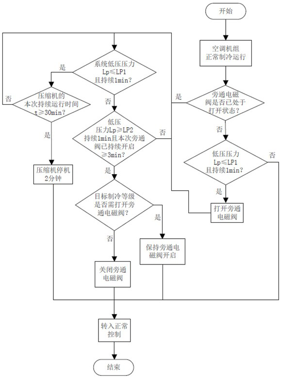
[0043] See attached Image 6 , different from Embodiment 1, the step of entering the pressure drop and exiting the step of pressure drop in this embodiment is based on the evaporation temperature sensor 11 arranged at the evaporator 6 .
[0044] Specifically, the step of entering the pressure ...
PUM
 Abstract
Description
Claims
Application Information
 - R&D
- Intellectual Property
- Life Sciences
- Materials
- Tech Scout
- Unparalleled Data Quality
- Higher Quality Content
- 60% Fewer Hallucinations
Browse by: Latest US Patents, China's latest patents, Technical Efficacy Thesaurus, Application Domain, Technology Topic, Popular Technical Reports.
© 2025 PatSnap. All rights reserved.Legal|Privacy policy|Modern Slavery Act Transparency Statement|Sitemap|About US| Contact US: help@patsnap.com


