
Novel anti-seismic steel structure

A new type of anti-seismic steel technology, applied in anti-seismic, building components, building types, etc., can solve the problems of reducing the stability of the connection between the main beam and the support column, the inability to limit the position of the spring and the elastic column, and the inability to effectively disperse the pressure of the main beam. , to achieve the effect of preventing the spring from skewing, avoiding collapse and improving stability

Inactive Publication Date: 2020-04-21
南通海驹钢结构有限公司
View PDF0 Cites 1 Cited by
  • Summary
  • Abstract
  • Description
  • Claims
  • Application Information

AI Technical Summary

Problems solved by technology

[0006] Aiming at the deficiencies of the prior art, the present invention provides a new type of anti-seismic steel structure, which solves the problem that the pressure of the main girder cannot be effectively dispersed when the steel structure is used, and the stability of the connection between the main girder and the supporting column is reduced, and the connection is not stable. Stability can easily lead to the defect of steel structure collapse. In addition, the spring and elastic column cannot be effectively limited, and the reverse elastic force generated when the spring and elastic column are compressed cannot always be on the same line as the direction of the pressure, which is easy to cause The spring is skewed

Method used


Image

  • Novel anti-seismic steel structure
  • Novel anti-seismic steel structure
  • Novel anti-seismic steel structure

Examples


Embodiment Construction

[0023] The following will clearly and completely describe the technical solutions in the embodiments of the present invention with reference to the accompanying drawings in the embodiments of the present invention. Obviously, the described embodiments are only some, not all, embodiments of the present invention. Based on the embodiments of the present invention, all other embodiments obtained by persons of ordinary skill in the art without making creative efforts belong to the protection scope of the present invention.

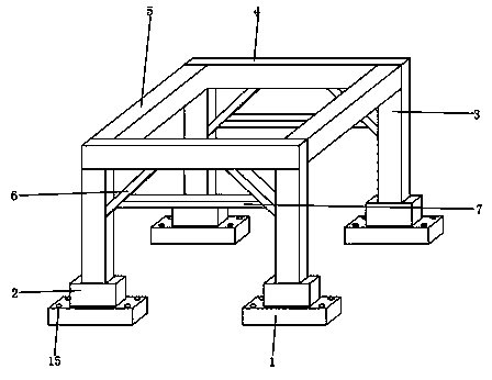
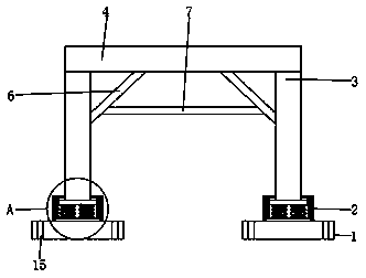
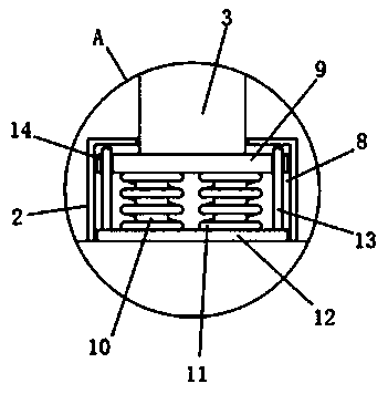
[0024] see Figure 1-4 , in this embodiment: a new type of anti-seismic steel structure, including a base 1, the upper end of the base 1 is provided with a fixed seat 2, the upper end of the fixed seat 2 is provided with a support column 3, and the upper end of the support column 3 is provided with a main beam 4. One side of the beam 4 is provided with a connecting beam 5, one side of the support column 3 is provided with a slanted support plate 6, one side of...


PUM


Abstract

The invention belongs to the technical field of steel structures, and particularly relates to a novel anti-seismic steel structure which comprises a base. The upper end of the base is provided with afixing seat, the upper end of the fixing seat is provided with a supporting column, the upper end of the supporting column is provided with a main beam, one side of the main beam is provided with a connecting beam, one side of the supporting column is provided with an inclined supporting plate, one side of the inclined supporting plate is provided with an abutting plate, and an empty groove is formed in the fixing seat. A first fixing plate is arranged at the bottom end of the supporting column, an elastic column is arranged at the lower end of the first fixing plate, and the outer surface wall of the elastic column is sleeved with a spring. The inclined supporting plate and the abutting plate are additionally arranged, so that the pressure of the main beam can be effectively dispersed bythe inclined supporting plate and the abutting plate, and the connection stability between the main beam and the supporting column is improved; and by additionally arranging a positioning rod and a positioning groove, the spring and the elastic column can be effectively limited, and the reverse elastic force generated when the spring and the elastic column are compressed can always be in the samestraight line with the direction of pressure.

Description

technical field [0001] The invention relates to the technical field of steel structures, in particular to a novel anti-seismic steel structure. Background technique [0002] Steel structure is a structure composed of steel materials, which is one of the main types of building structures. The structure is mainly composed of beam steel, steel column, steel truss and other components made of section steel and steel plate, and adopts rust removal and antirust processes such as silanization, pure manganese phosphating, washing and drying, and galvanizing. The components or components are usually connected by welds, bolts or rivets. Because of its light weight and easy construction, it is widely used in large factories, stadiums, super high-rises and other fields. It is a new type of steel structure. [0003] The following problems exist: [0004] 1. When the steel structure is used, the pressure of the main beam cannot be effectively dispersed, which reduces the stability of t...

Claims


Application Information

Patent Timeline
Patent Type & Authority Applications(China)
IPC IPC(8): E04B1/24E04H9/02E04B1/98
CPCE04B1/24E04B1/98E04H9/021E04H9/024
Inventor 谢海居
Owner 南通海驹钢结构有限公司
Learn More