Bridge abutment construction method

A construction method and abutment technology, applied to excavation, bridges, bridge parts, etc., can solve the problems of large construction site, large excavation height, loose slope, etc., achieve small construction site, avoid reduction of bearing capacity, reduce cracking effect

Inactive Publication Date: 2020-04-21
ROAD & BRIDGE INT +1
View PDF5 Cites 2 Cited by
  • Summary
  • Abstract
  • Description
  • Claims
  • Application Information

AI Technical Summary

Problems solved by technology

[0003] Therefore, the technical problem to be solved by the present invention is to overcome the defect that the bottom of the abutment access tunnel in the prior art is excavated to the bottom at one time, the excavation height is large, the construction site is large, and if the side slope is loose, it is easy to cause slide and collapse, thereby providing a Abutment construction method

Method used


Image

  • Bridge abutment construction method
  • Bridge abutment construction method

Examples


Embodiment 1

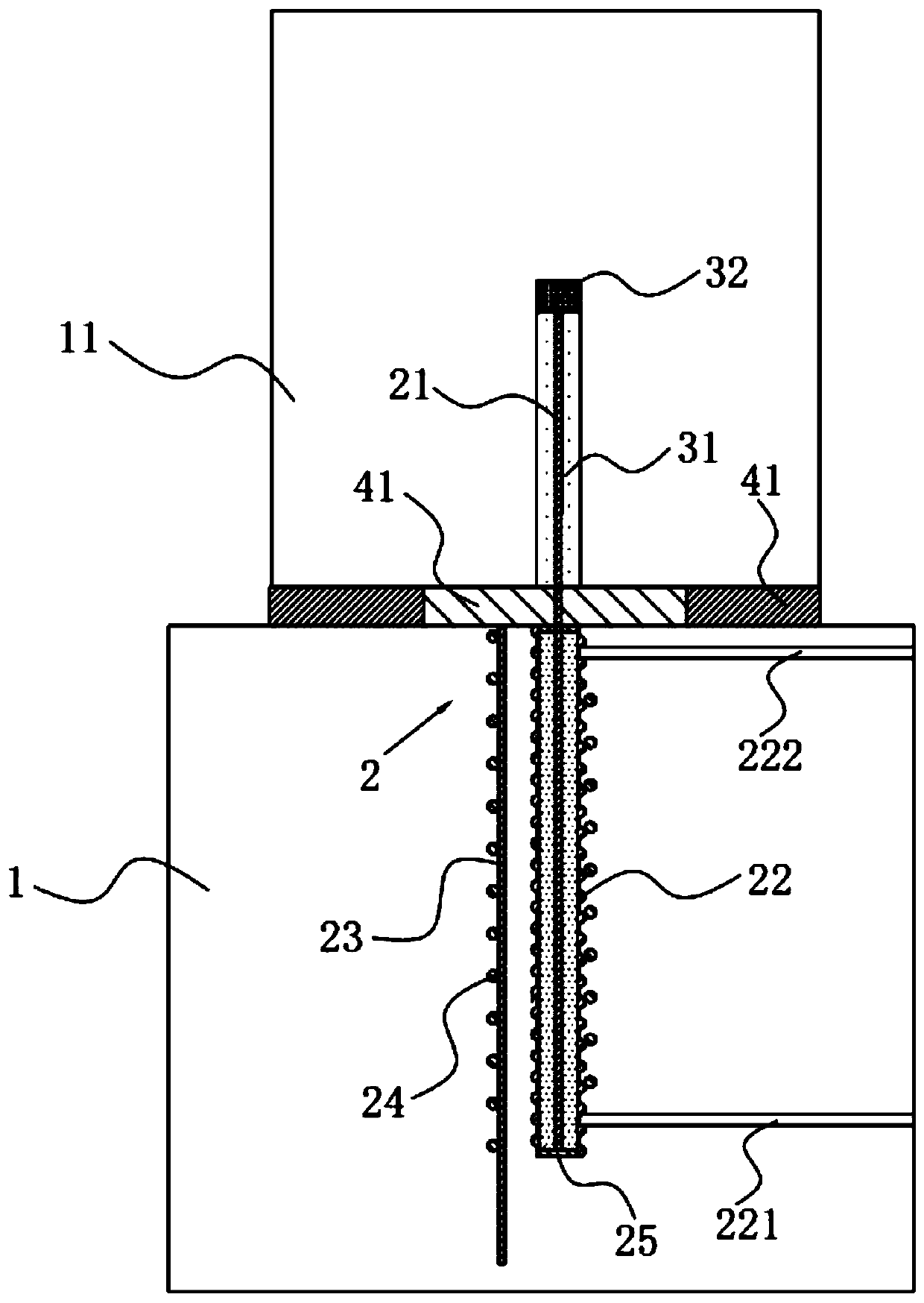
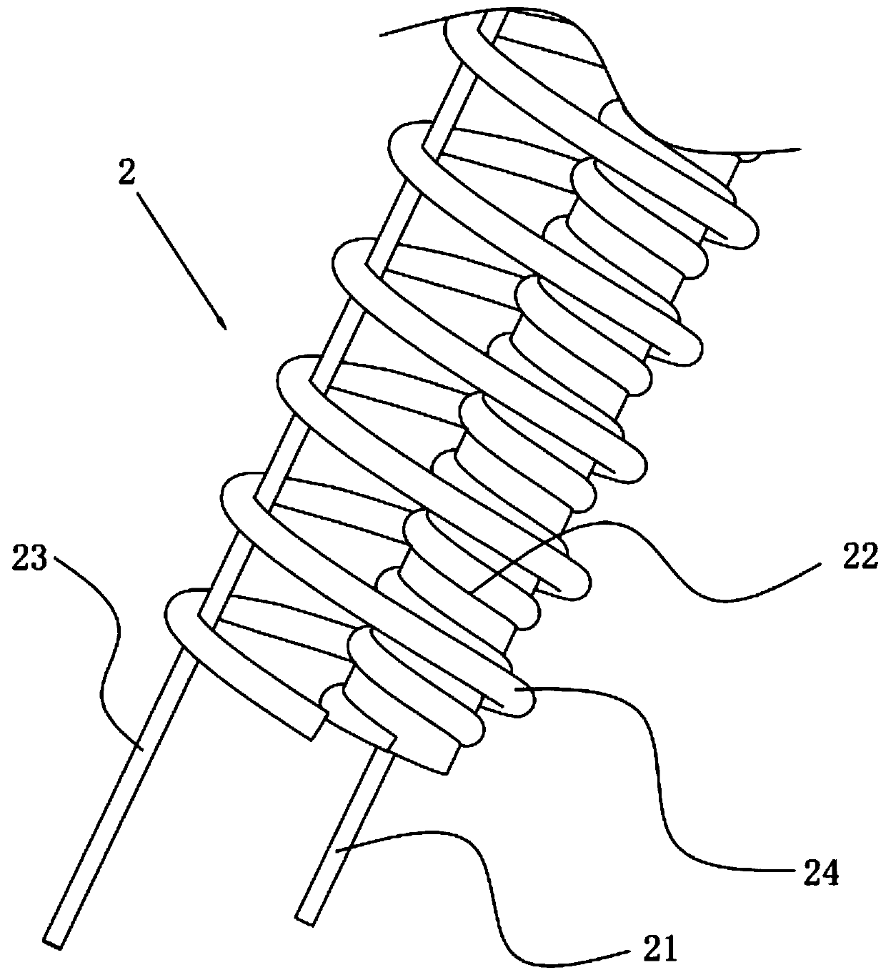
[0040] An abutment structure such as figure 1 As shown, including platform 1 , there is platform body 11 above platform 1 , platform body 11 is rotatably connected with platform 1 through connector 2 , specifically, platform body 11 is located on the top surface of platform 1 . In order to reduce the constraint displacement caused by the temperature load, reduce the lateral (along the width direction of the platform 1) and lateral (along the length direction of the platform 1) displacement of the platform 1, and reduce the influence of the instantaneous displacement of the platform body 11 on the platform 1, the platform The connection between the body 11 and the cap 1 is designed to be rotatable and hinged, so that the influence of the superstructure (that is, the platform body 11) on the pile foundation (that is, the cap 1) can be transferred, part of the rotational kinetic energy can be released, and large damage to the pile foundation can be avoided. Lateral displacement a...

Embodiment 2

[0049] A kind of bridge abutment construction method, at first artificially removes the dangerous stone on the side slope outside the tunnel, temporarily supports the side slope (back pressure, filling joints and anchor spray support), cleans up the loose body of the side slope outside the tunnel, and opens the foundation trench Excavation (excavation to the bottom of the cap), construction of excavated piles, construction of the cap, construction of the platform body, permanent support of the slope (grid beam anchor cable).

[0050] The specific construction method is:

[0051] S1. First, clean up the dangerous stones on the slope outside the tunnel, and then seal them with plain spray C25 concrete. The thickness of the spray is 8cm;

[0052] S2. Bolt and shotcrete support is carried out on the outer side slope of the tunnel from top to bottom. The anchor rod adopts φ22mm mortar bolt. Net, the grid spacing of the steel mesh is 20cm×20cm, connect the steel mesh to the mortar ...


PUM


Abstract

The invention relates to the technical field of bridge engineering, and particularly relates to a bridge abutment construction method. In the prior art, a bridge abutment entering tunnel bottom is excavated to the bottom at one time, excavation height is large, construction site is large, if the side slope is loose, slump is easily caused. The bridge abutment construction method is characterized by comprising the following steps: cleaning tunnel outer side upward slope dangerous rock; carrying out anchor-plate retaining on the outer side slope of the tunnel; constructing foot locking anchor pipes on second lining portions on the two sides of an abutment front beam groove, additionally arranging temporary supports on the left side wall and the right side wall of a tunnel second lining, adopting step-by-step excavation for bridge abutment construction in the tunnel, adopting a concrete retaining wall excavation scheme for hole digging piles from left to right, carrying out segmental excavation, excavating one support , and carrying out concrete pouring after excavation to the designed elevation; pouring bearing platform concrete at a time, and arranging surface protection ribs on four side faces of the bearing platform; and pouring the platform body concrete in two times, wherein the first pouring height is the height of the bottom surface of the padstone, and the second pouringheight reaches the designed elevation. The method has the advantages that the construction site is small, and the slump phenomenon is prevented in segmented construction.

Description

technical field [0001] The invention relates to the technical field of bridge engineering, in particular to an abutment construction method. Background technique [0002] At present, the construction of the abutment at the exit of the tunnel is to excavate the abutment to the bottom of the tunnel at one time. The excavation height is large, and the construction site is large. If the side slope is loose, it will cause slipping and collapse, which poses a safety hazard. Contents of the invention [0003] Therefore, the technical problem to be solved by the present invention is to overcome the defect that the bottom of the abutment access tunnel in the prior art is excavated to the bottom at one time, the excavation height is large, the construction site is large, and if the side slope is loose, it is easy to cause slide and collapse, thereby providing a Bridge abutment construction methods. [0004] Above-mentioned technical purpose of the present invention is achieved thro...

Claims


Application Information

Patent Timeline
Patent Type & Authority Applications(China)
IPC IPC(8): E01D21/00E02D17/20E02D5/76E01D19/02E02D27/42E02D27/14
CPCE01D19/02E01D21/00E02D5/76E02D17/20E02D27/14E02D27/42
Inventor 吴曼葛纪平白松侯兆隆康笠
Owner ROAD & BRIDGE INT
Why Eureka
Try Eureka