
Composite material main lifting support and manufacturing and assembling method thereof

A composite material and support plate technology, which is applied in aircraft assembly, transportation and packaging, chassis, etc., can solve the problems of heavy main support, complicated manufacturing process, laborious operation, etc., to improve the strength of the connection structure, strong general performance, Flexible effects

Inactive Publication Date: 2020-04-21
天津爱思达新材料科技有限公司
View PDF6 Cites 2 Cited by
  • Summary
  • Abstract
  • Description
  • Claims
  • Application Information

AI Technical Summary

Problems solved by technology

[0006] The purpose of the present invention is to provide a composite material main bracket to solve the existing problems in the prior art. The main bracket is made of metal, and the overall weight is heavy; two hydraulic rods and wheel hubs are used to support the main bracket. Technical problems of heavy weight, laborious operation, and poor general performance
[0007] The purpose of the present invention is to provide a method for manufacturing and assembling composite main lifting brackets, so as to solve the technical problems existing in the prior art, such as adopting wheel hub supports and hydraulic damping supports, complicated manufacturing process and low production efficiency

Method used


Image

  • Composite material main lifting support and manufacturing and assembling method thereof
  • Composite material main lifting support and manufacturing and assembling method thereof
  • Composite material main lifting support and manufacturing and assembling method thereof

Examples


Embodiment Construction

[0048] It should be noted that, in the case of no conflict, the embodiments of the present invention and the features in the embodiments can be combined with each other.

[0049] In describing the present invention, it should be understood that the terms "center", "longitudinal", "transverse", "upper", "lower", "front", "rear", "left", "right", " The orientations or positional relationships indicated by "vertical", "horizontal", "top", "bottom", "inner" and "outer" are based on the orientations or positional relationships shown in the drawings, and are only for the convenience of describing the present invention and Simplified descriptions, rather than indicating or implying that the device or element referred to must have a particular orientation, be constructed and operate in a particular orientation, and thus should not be construed as limiting the invention. In addition, the terms "first", "second", etc. are used for descriptive purposes only, and should not be understood ...


PUM

PropertyMeasurementUnit
Thicknessaaaaaaaaaa
Thicknessaaaaaaaaaa

Abstract

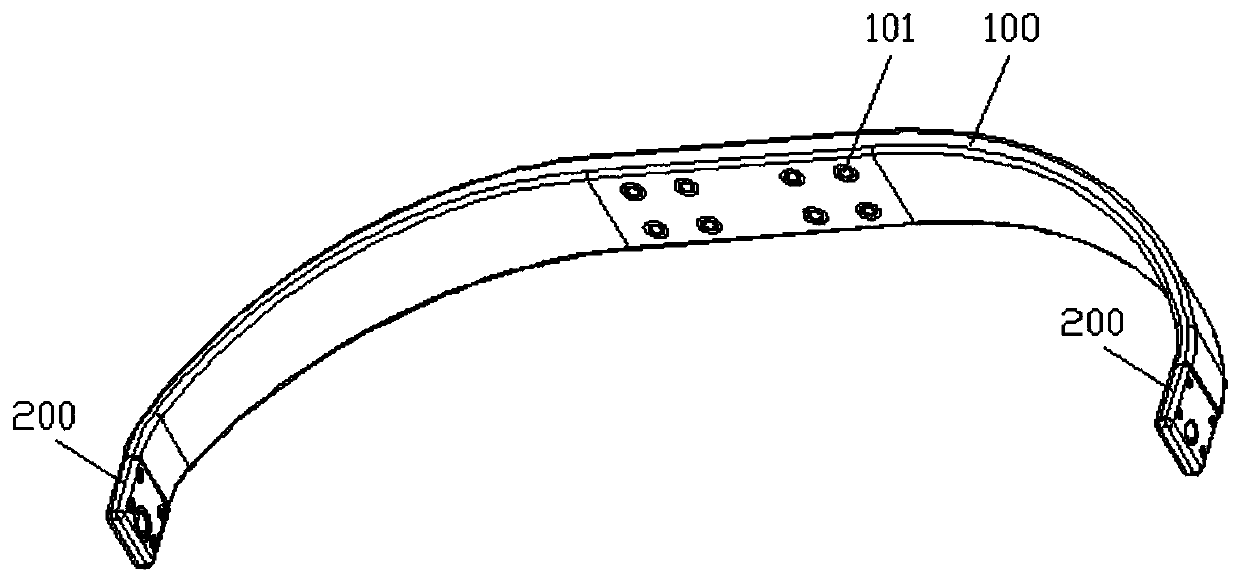
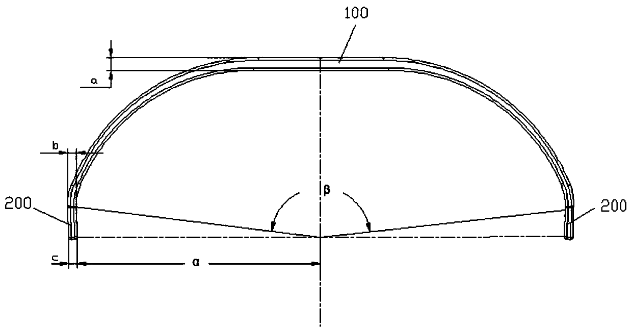
The invention discloses a composite material main lifting support and a manufacturing and assembling method thereof, and belongs to the technical field of aviation aircraft accessories. The compositematerial main lifting support comprises an arc-shaped plate and two side supporting plates; the arc-shaped plate and the side supporting plates are made of composite materials, and the arc-shaped plate and the side supporting plates are integrally formed; the arc-shaped plate is used for being connected with the lower portion of a fuselage of an aircraft, and the two side supporting plates are connected to the two end faces of the arc-shaped plate respectively and used for being connected with two hubs respectively. The problems that in the prior art, a main lifting support is made of a metalmaterial, and the overall weight is large; and two hydraulic rods and a hub supporting mode are adopted, the weight of a main lifting support is large, operation is strenuous, and the universality ispoor are solved. The arc-shaped plate and the side support plates are made of composite materials, so that the overall weight is light; the two ends of the arc-shaped plate are each connected with onecorresponding side supporting plate, each side supporting plate is connected with a corresponding hub, and the whole support is light in weight and good in universality.

Description

technical field [0001] The invention relates to the technical field of aviation aircraft accessories, in particular to a composite material main lifting bracket and a manufacturing and assembling method thereof. Background technique [0002] The main landing gear is an accessory device at the lower part of the aircraft used to take off, land, support the aircraft when taxiing on the ground, and move on the ground. It is an indispensable part of the aircraft. In the process of safe take-off and landing of aviation aircraft, it shoulders an extremely important mission. [0003] In the prior art, the main landing gear adopts the structure of hydraulic rods, that is, two hydraulic rods are used, the upper ends of the two hydraulic rods are connected to the lower part of the fuselage of the aircraft, and the lower ends of the two hydraulic rods are respectively connected to the left wheel hub and the right wheel hub. . The use of two hydraulic rods not only supports the body of...

Claims


Application Information

Patent Timeline
IPC IPC(8): B64C25/02B64F5/10
CPCB64C25/02B64C2001/0072B64F5/10
Inventor 王非唐占文刘发杰刘含洋丁常方
Owner 天津爱思达新材料科技有限公司
Learn More