Forming and machining device for transformer heat radiation pipes

A technology of molding processing and heat dissipation pipes, which is applied in the field of transformer processing, can solve the problems of reducing the service life of heat dissipation pipes, scratches on the surface of heat dissipation pipes, and easy damage to heat dissipation pipes, so as to reduce friction, improve work efficiency, and prevent falling off Effect

Inactive Publication Date: 2020-04-21
广西陆川祥进电子科技有限公司
View PDF8 Cites 1 Cited by
  • Summary
  • Abstract
  • Description
  • Claims
  • Application Information

AI Technical Summary

Problems solved by technology

[0004] (1) After processing the heat pipes of traditional transformer heat pipes, the heat pipes need to be sorted when they are used later, and the structural shape of the heat pipes results in being dragged by other heat pipes when the heat pipes are taken out. , and scratch the surface of the heat pipe, and even deform the heat pipe
[0005] (2) When the traditional transformer cooling tube forming processing device processes the cooling tube, the surface of the cooling tube is prone to scratches, and the use environment of the cooling tube makes the scratched cooling tube more likely to be damaged, thereby reducing the heat dissipation of the cooling tube. service life

Method used


Image

  • Forming and machining device for transformer heat radiation pipes
  • Forming and machining device for transformer heat radiation pipes
  • Forming and machining device for transformer heat radiation pipes

Examples


Embodiment Construction

[0031] In order to make the technical means realized by the present invention, creative features, goals and effects easy to understand, the following combination Figure 1 to Figure 6 , to further elaborate the present invention.

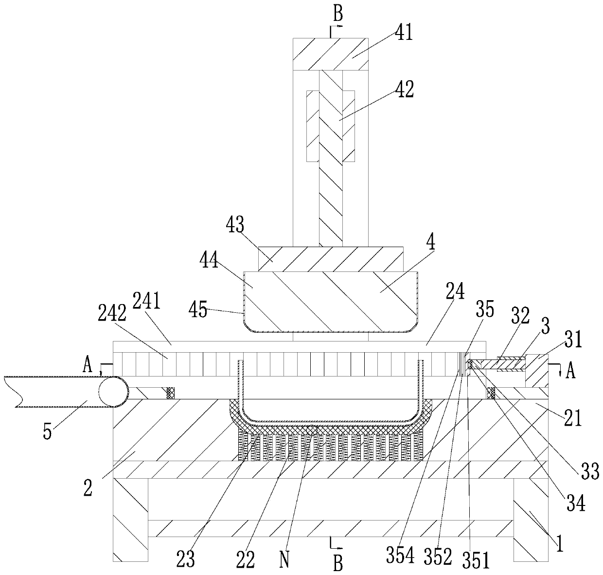
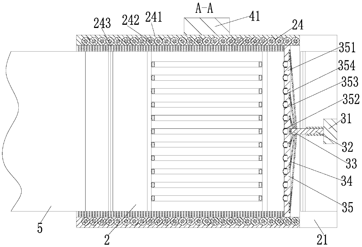
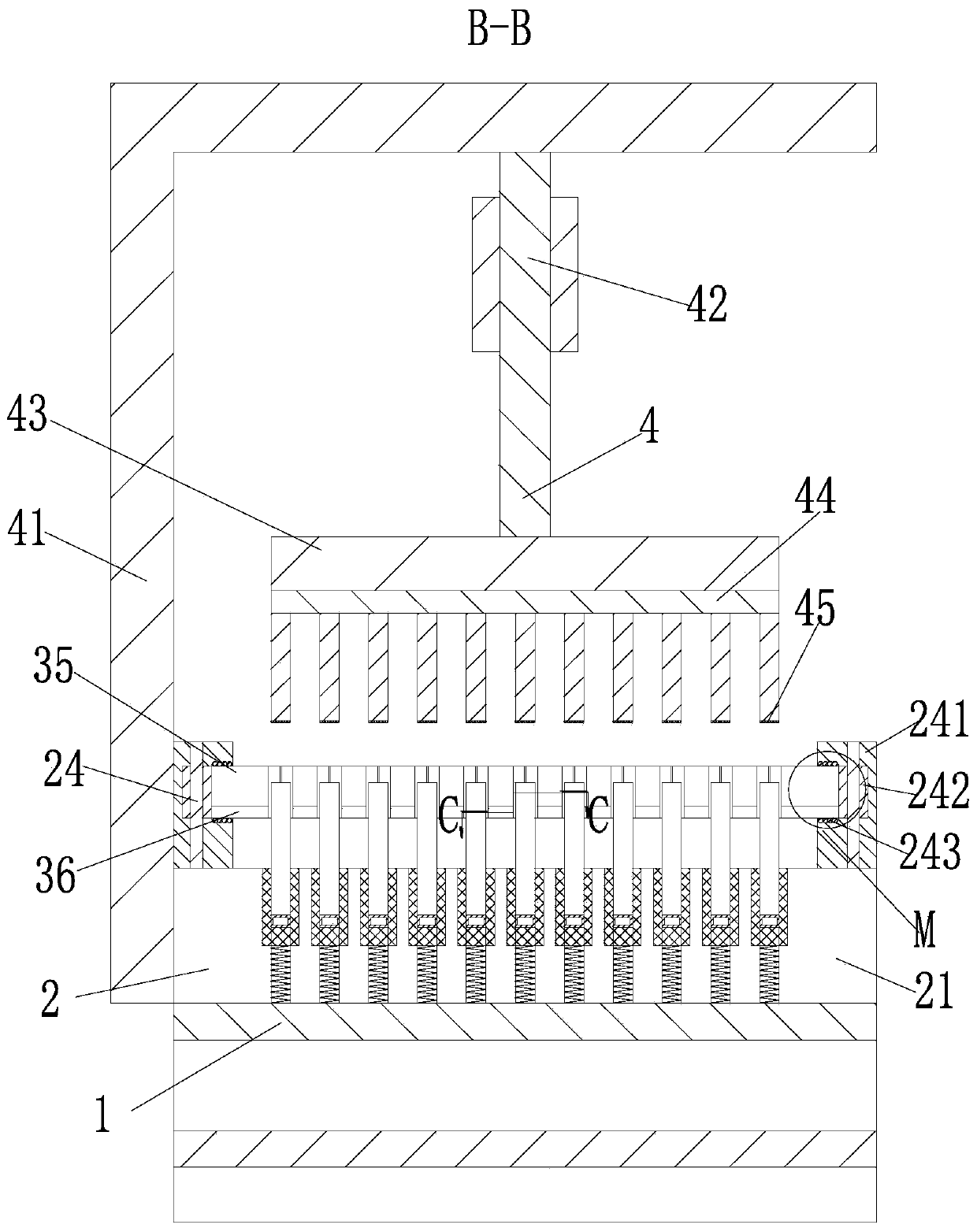
[0032] A transformer cooling tube molding processing device, comprising a workbench 1, a fixing device 2, a pusher device 3, a forming device 4 and a belt conveyor 5, the upper end of the workbench 1 is fixedly installed with a fixing device 2, and the fixing device 2 A pusher device 3 is installed on the upper end, a forming device 4 is installed on the front end of the fixing device 2, and a belt conveyor 5 is installed on the left end of the fixing device 2; wherein:

[0033] The fixing device 2 includes a fixing plate 21, a large cylindrical spring 22, a rubber block 23 and a sliding track 24. The upper end of the workbench 1 is fixed with a fixing plate 21, and the lower end of the fixing plate 21 is uniformly provided with a cylindrical hole, ...


PUM


Abstract

The invention relates to a forming and machining device for transformer heat radiation pipes. The forming and machining device comprises a workbench, a fixed device, a part pushing device, a forming device and a belt conveyor. The fixed device is fixedly mounted on the upper end face of the workbench. The part pushing device is mounted at the upper end of the fixed device. The forming device is mounted at the front end of the fixed device. The belt conveyor is mounted at the left end of the fixed device. The part pushing device comprises a fixed block, an electric push rod, an umbrella-shapedframe, an arc magnet, a rectangular plate and a rectangular magnet. According to the forming and machining device, un-machined heat radiation pipes are located through the fixed device, the heat radiation pipes are formed and machined through a shaping device, the part pushing device is used for locating and conveying the machined heat radiation pipes, and therefore the situation that pulling is generated when the heat radiation pipes are taken out and consequently the quality of the heat radiation pipes is influenced is avoided; and the fixed device and the shaping device protect the surfacesof the heat radiation pipes so as to prevent scratches from being generated on the surfaces of the heat radiation pipes.

Description

technical field [0001] The invention relates to the technical field of transformer processing, in particular to a forming and processing device for a heat dissipation tube of a transformer. Background technique [0002] With the rapid development of the power industry, the demand and requirements of transformers are gradually increasing. Transformers are prone to generate heat during use, which affects the efficiency of transformers and even reduces the life of transformers. Therefore, heat pipes are used during the use of transformers When the oil in the transformer is heated, it rises into the heat dissipation pipe, and the temperature of the transformer oil is cooled by the outside air or other media. After the transformer oil is cooled, it descends and enters the transformer oil tank again for use. [0003] In the process of processing the heat sink of the transformer, due to the structural limitations of the heat sink, the following problems exist in the actual operatio...

Claims


Application Information

Patent Timeline
Patent Type & Authority Applications(China)
IPC IPC(8): B21D43/00B21D45/02B21D53/06B21D45/00
CPCB21D43/003B21D45/00B21D45/02B21D53/06
Inventor 孙远远
Owner 广西陆川祥进电子科技有限公司
Why Eureka
Try Eureka