
Device for detecting inner wall defects of cylinder

A technology for detecting pillars and defects, applied in telescopes, optics, instruments, etc., can solve problems such as low efficiency, speckle, and large manpower, and achieve the effects of improving automation, increasing light brightness, and strong adjustability

Inactive Publication Date: 2020-04-17
SUZHOU LINGHOU ROBOT
View PDF12 Cites 4 Cited by
  • Summary
  • Abstract
  • Description
  • Claims
  • Application Information

AI Technical Summary

Problems solved by technology

[0002] The measurement or inspection of the inner wall of cylinders and round tubes is a relatively difficult step in the inspection process in the field of mechanical processing. It is mainly limited by the lack of space and light, which makes it impossible to use outer wall measurement tools for the inner walls of cylinders and round tubes.
[0003] At present, many manufacturers use manual inspection methods when detecting small-sized cylinder inner wall defects, that is, use a magnifying glass dozens of times to observe the inner wall. This method not only consumes a lot of manpower, but also is inefficient.
When using commonly used visual light sources such as coaxial light sources and ring light sources, for cylindrical workpieces with small diameters and deep depths, this type cannot uniformly illuminate the inner wall of the cylinder, resulting in the inability of the visual software to judge defects
There will be speckles in the laser method, which will affect the judgment of defects

Method used


Image

  • Device for detecting inner wall defects of cylinder
  • Device for detecting inner wall defects of cylinder
  • Device for detecting inner wall defects of cylinder

Examples


Embodiment

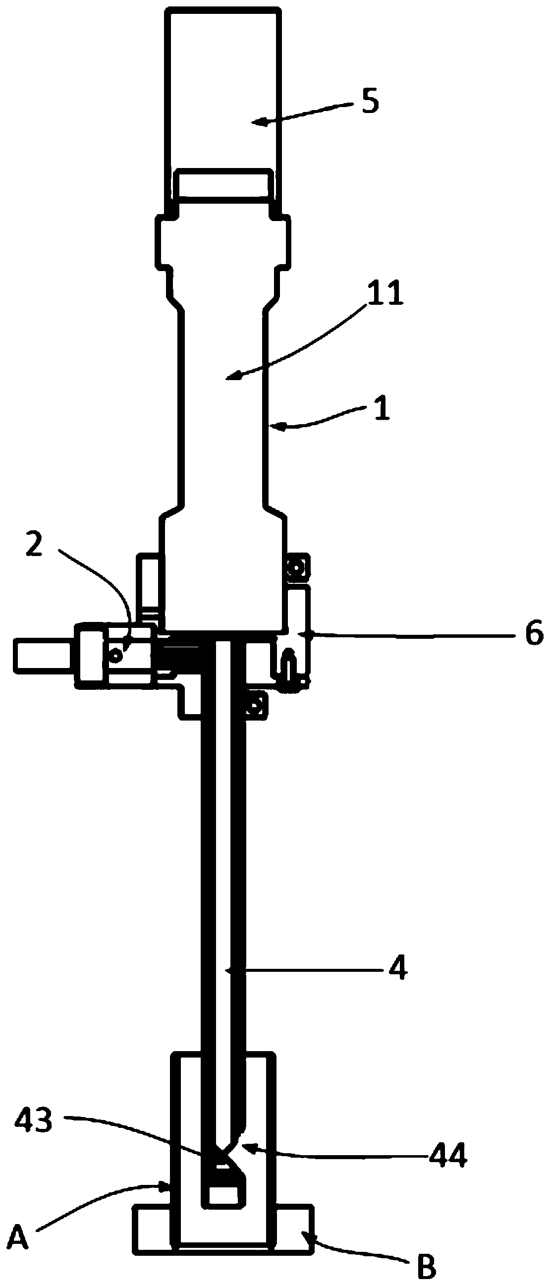
[0049] This embodiment provides a device for detecting defects on the inner wall of a column, such as Figure 1-3 shown, including:

[0050] The lens 1 has a channel 11 inside to allow light to pass through;

[0051] light source 2;

[0052] Probe tube 4, one end is connected to one end of described lens 1, and the inside of the other end is provided with light deflection assembly 43, and described probe tube 4 is provided with opening 44 at the place that aligns with described light deflection assembly 43; The light outside the tube 4 can enter the inside through the opening 44 and pass through the light deflecting assembly 43 and then transmit along the axial direction of the channel 11;

[0053] An optical fiber 3, the optical fiber 3 is arranged in the probe tube 4, one end is connected to the light source 2, and the other end is exposed from the edge of the opening 44 of the probe tube 4, so that the light emitted by the light source 2 can travel along the The optical ...


PUM


Abstract

The invention relates to a device for detecting defects of an inner wall of a cylinder. The device comprises a lens, a light source, an exploring tube and a camera assembly, the lens is internally provided with a channel for light to pass through, one end of the exploring tube is connected with one end of the lens, a light deflection assembly is arranged at the other end of the exploring tube, anopening is formed at the position, aligned with the light deflection assembly, of one side of the exploring tube, light outside the exploring tube can enter the exploring tube from the opening and pass through the light deflection assembly to be transmitted in the axis direction of the channel, the optical fiber is arranged in the probe tube, one end is connected with the light source, the other end is exposed from an opening edge of the probe tube, so the light emitted by the light source can irradiate along the optical fiber, the camera assembly is connected with the other end of the lens and located on the opposite side of the probe, and the shooting direction of the camera assembly is aligned with the channel axis direction. The device is advantaged in that a problem that images of aninner wall of a small-diameter and long-depth cylindrical workpiece are difficult to obtain is solved, the device is suitable for detecting the inner walls of transparent and non-transparent cylinders, and the automation level of a production line is improved.

Description

technical field [0001] The application belongs to the technical field of workpiece surface detection, and in particular relates to a device for detecting defects on the inner wall of a cylinder. Background technique [0002] The measurement or inspection of the inner wall of cylinders and tubes is a difficult step in the inspection process in the field of mechanical processing. It is mainly limited by the lack of space and light, which makes it impossible to use outer wall measurement tools for the inner walls of cylinders and tubes. [0003] At present, many manufacturers use manual inspection methods when detecting small-sized cylinder inner wall defects, that is, use a magnifying glass dozens of times to observe the inner wall. This method not only consumes a lot of manpower, but also is inefficient. When using commonly used visual light sources such as coaxial light sources and ring light sources, for small diameter and deep cylindrical workpieces, this type cannot evenl...

Claims


Application Information

Patent Timeline
Patent Type & Authority Applications(China)
IPC IPC(8): G02B23/24
CPCG02B23/2484G02B23/2469
Inventor 周师发李航宇
Owner SUZHOU LINGHOU ROBOT
Learn More