
Recyclable sound insulation unit convenient to disassemble

A convenient disassembly, square technology, applied in the direction of sound insulation, building components, construction, etc., can solve the problems of inconvenient disassembly, damage, unfavorable reuse, etc., and achieve the effect of convenient operation and convenient disassembly and assembly.

Pending Publication Date: 2020-04-17
四川贝强声学工程有限公司
View PDF0 Cites 3 Cited by
  • Summary
  • Abstract
  • Description
  • Claims
  • Application Information

AI Technical Summary

Problems solved by technology

Most of the existing sound insulation units are assembled side by side by tenon joint, and then two adjacent sound insulation units are fixed by bolts or glue to increase the strength. Such a structure is inconvenient to disassemble and is not conducive to reuse
[0003] Further, the mortise joint form of the existing sound insulation unit is generally through the tenon joint block and the tenon joint groove, and its side is perpendicular to the front of the sound insulation unit, so that after several sound insulation units are spliced ​​together, if a single sound insulation unit is under external force The damaged sound insulation unit can only be replaced after the surrounding sound insulation unit is removed.
That is to say, in the prior art, after the splicing of the sound insulation units has been completed, it is inconvenient to replace one of the independent sound insulation units.

Method used


Image

  • Recyclable sound insulation unit convenient to disassemble
  • Recyclable sound insulation unit convenient to disassemble
  • Recyclable sound insulation unit convenient to disassemble

Examples


Embodiment

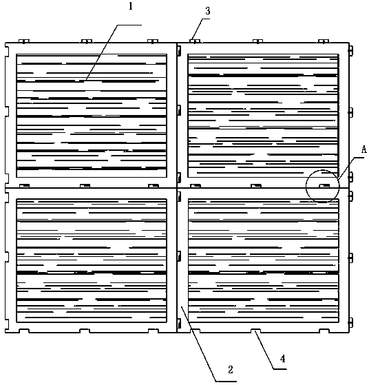
[0020] A reusable sound insulation unit 1 that is easy to disassemble includes a square frame, a panel, and a back panel. The panel and the back panel are fixed in the square outer frame by bolts, and the accommodation space between the panel and the back panel is filled with sound-insulating materials.

[0021] The upper and lower frames of the square outer frame are respectively provided with a connection structure A3 and a connection structure B4. The left and right borders of the square outer frame are respectively provided with a connecting structure A3 and a connecting structure B4.

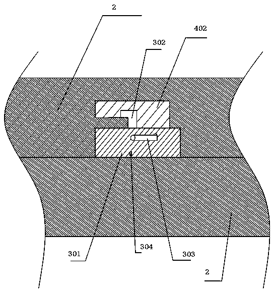
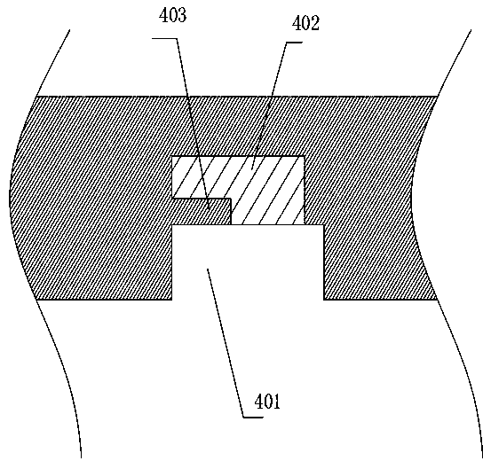
[0022] like figure 1 The connection structure A3 and the connection structure B4 on the square outer frame of the sound insulation unit 1 shown are respectively used for corresponding connection with the connection structure B4 and connection structure A3 of another sound insulation unit 1 .

[0023] Specifically, each frame is provided with a number of connection structures A3 that are e...


PUM


Abstract

The invention discloses a recyclable sound insulation unit convenient to disassemble. The sound insulation unit comprises a square outer frame and a sound insulation material arranged inside the square outer frame. The upper and lower frames of the square outer frame are provided with connecting structure A and a connecting structure B respectively. The left and right frames of the square outer frame are provided with a connecting structure A and a connecting structure B respectively. The connecting structures A and the connecting structures B on the square outer frame of the sound insulationunit are used for being correspondingly connected with the connecting structures B and the connecting structures A of another sound insulation unit. Each connecting structure A comprises a limiting boss and a rotating locking mechanism, wherein the rotating locking mechanism comprises a rotating arm, a rotating shaft and a locking plate, the limiting boss is of a hollow structure with the open top, the rotating shaft is rotationally arranged between the inner side walls of the limiting bosses, one end of the rotating shaft stretches out of the corresponding limiting boss to be fixedly connected with the rotating arm, and the rotating shaft is sleeved with the corresponding locking plate. Each connecting structure B comprises a limiting groove and a locking groove, wherein the notch of thelocking groove communicates with the groove bottom of the limiting groove, and a locking table is formed at the joint of the locking groove and the limiting groove.

Description

technical field [0001] The invention relates to a sound insulation unit, in particular to a reusable sound insulation unit which is easy to disassemble. Background technique [0002] A soundproof wall or soundproof room is generally made up of multiple soundproof units. Most of the existing sound insulation units are assembled side by side by mortise joints, and then two adjacent sound insulation units are fixed by bolts or glue to increase the strength. Such a structure is inconvenient to disassemble and is not conducive to reuse. [0003] Further, the mortise joint form of the existing sound insulation units is generally through the tenon joint block and the tenon joint groove, and its side is perpendicular to the front of the sound insulation unit, so that after several sound insulation units are spliced ​​together, if a single sound insulation unit The damaged sound insulation unit can only be replaced after the surrounding sound insulation unit is removed. That is, in...

Claims


Application Information

Patent Timeline
IPC IPC(8): E04B1/84E04B1/86E04B1/61
CPCE04B1/6137E04B1/6141E04B1/8227E04B1/84E04B1/86E04B2001/8423
Inventor 张正斌
Owner 四川贝强声学工程有限公司
Learn More