
Vehicle emergency brake protection system and method

A protection system and vehicle technology, applied in the field of vehicle emergency braking protection system, can solve problems such as bumping, rolling over, collision of vehicles ahead or obstacles, etc., achieving the effects of good versatility, reduced damage and simple composition

Active Publication Date: 2020-04-17
NANJING TOP SUN TECH
View PDF6 Cites 1 Cited by
  • Summary
  • Abstract
  • Description
  • Claims
  • Application Information

AI Technical Summary

Problems solved by technology

[0002] In the activities of driving a vehicle, it is often necessary to perform emergency braking on the vehicle. Since the emergency braking requires the vehicle to run at a higher speed and achieve the need to decelerate or even stop in as short a time as possible, during emergency braking, When the braking force of the vehicle is too large, the mechanical structure of the vehicle and the occupants of the vehicle will be subjected to a large impulse, resulting in damage to the structure of the vehicle and causing great discomfort to the occupants of the vehicle. In addition, when the speed of the vehicle is not proportional to the distribution of the braking force of the vehicle, on the one hand, it is easy to cause the vehicle to brake in time and cause a serious collision with the vehicle or obstacle in front, and on the other hand, it is easy to cause the vehicle to slip and flick In severe cases, it may even cause accidents such as turning over, which seriously affects the safety of vehicle operation.

Method used


Image

  • Vehicle emergency brake protection system and method
  • Vehicle emergency brake protection system and method
  • Vehicle emergency brake protection system and method

Examples


Embodiment Construction

[0020] For introducing the present invention in more detail, the present embodiment is set forth as follows:

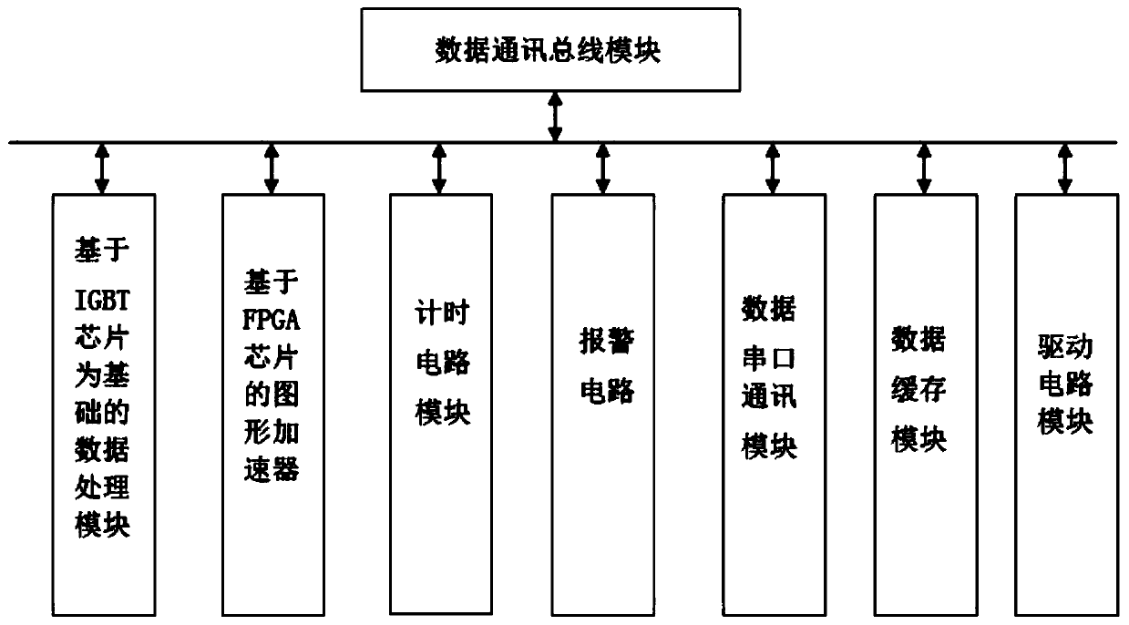
[0021] Such as figure 1 , 2 As shown in and 3, a vehicle emergency braking protection system includes a front body detection mechanism 1, a rear body detection mechanism 2, a brake detection mechanism 3 and a main control system 4, wherein the front body detection mechanism 1, the rear body The detection mechanism 2 is respectively connected with the front of the vehicle and the body of the parking space, the brake detection mechanism 3 is connected with the vehicle braking system, and the front body detection mechanism 1, the rear body detection mechanism 2, and the brake detection mechanism 3 are all connected with the main control system. 4 Electrical connection, the main control system 4 is embedded in the vehicle center console and electrically connected with the vehicle driving computer system.

[0022] In this embodiment, the front vehicle body detection mech...


PUM


Abstract

The invention relates to a vehicle emergency brake protection system. The system comprises a front vehicle body detection mechanism, a rear vehicle body detection mechanism, a brake detection mechanism and a main control system, wherein the front vehicle body detection mechanism and the rear vehicle body detection mechanism are connected with a vehicle head and a parking space vehicle body respectively; the brake detection mechanism is connected with a vehicle brake system; the front vehicle body detection mechanism, the rear vehicle body detection mechanism and the brake detection mechanism are all electrically connected with a main control system; the main control system is embedded in a vehicle center console and electrically connected with a vehicle ECU system. A protection method comprises three steps of equipment hardware assembly, software driving, braking judgment and protection. On one hand, the requirements of operation of various vehicles can be effectively met; and on the other hand, detection and protection are achieved, braking force distribution during emergency braking of the vehicle can be accurately controlled from multiple angles in combination with the actual running rotary table of the vehicle, and damage to personnel in the vehicle and damage to the vehicle during braking of the vehicle are effectively reduced while the vehicle braking requirement is met.

Description

technical field [0001] The invention relates to a vehicle emergency braking protection system and method, belonging to the technical field of traffic monitoring. Background technique [0002] In the activities of driving a vehicle, it is often necessary to perform emergency braking on the vehicle. Since the emergency braking requires the vehicle to run at a high speed and achieve the need to decelerate or even stop in the shortest possible time, during emergency braking, When the braking force of the vehicle is too large, the mechanical structure of the vehicle and the occupants of the vehicle will be subjected to a large impulse, resulting in damage to the structure of the vehicle, causing great discomfort to the occupants of the vehicle, and even causing injuries to the occupants of the vehicle in severe cases. In addition, when the speed of the vehicle is not proportional to the distribution of the braking force of the vehicle, on the one hand, it is easy to cause the veh...

Claims


Application Information

Patent Timeline
Patent Type & Authority Applications(China)
IPC IPC(8): B60T7/12B60W30/18
CPCB60T7/12B60W30/18109B60W30/18172B60W2420/408B60W2420/403
Inventor 田海霞
Owner NANJING TOP SUN TECH
Learn More